Making a new thread because where we started and where we are now is 2 completely different places lol.
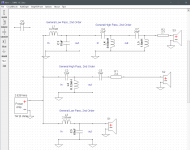
I'm currently looking at making a 3 way big bookshelf speaker that uses a DSA270-8 woofer, a RS52FN-8 mid and a RST28F-4. Crossed at 900 ish and 3400 ish in xsim. This is the best i could get in this program.
Hows it look, any suggestions? Am I a moron?? lol i really dont know much about this subject so any input is appreciated, thanks everyone.
Attachments
Last edited:
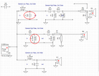
Your schematic shows the S3 driver having a 4th-order HPF, but is labelled '2nd-order'.
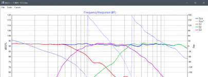
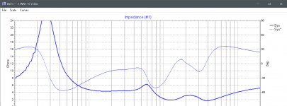
The impedance graph shows below 4 ohms from 850 to 10kHz, but I don't see how unless R1 and R2 are 2.4 and 2.7, instead of 24 and 27 ohms (can't tell for sure looking at it). An L-pad would be better. Also, some amps will have trouble with an impedance that low. Any chance that XSim doesn't know enough about your drivers?
Often w/2nd-order filters, adjacent drivers have their polarity flipped -- gives smoother transitions.
Cheers
edit: I see you already got the note about mid polarity. 😱
Last edited:
Is there a need to cross each driver somewhere, or are they just overlapping on a baffle? Have you been watching phase while doing this, you might be introducing a little inconsistency. I'd check your data, look at the impedance of each way separately.
Ok im going to try and answer all the questions.
1st - it says 2nd order because i used the 2nd order template and the label stays when you add more stuff to it. It gives a nice ui to get it close and then you individually change the components after that. I am very new to this so im just going willy nilly over here haha.
2nd - I dont really know how i can fix these ohm issues without massively changing the frequency curve drastically. Very slight changes to the components yield small gains for the ohm situation and completely nuke the frequency curve. Any suggestions?
3rd - Doesnt the resistor in line and resistor crossed between pos and neg mimic what a L pad is/does?
4th - I added the FRD and ZMA files? is there any more i should be adding to do this right?
5th - Im not quite sure what you mean when you ask if its over lapped on a baffle. The only reason i am crossing these where they are is because the drivers either have a nasty dip or hump in the frequency curve if they are crossed anywhere else. This is about the best i could get the line, if that answers your question at all idk sorry. I really dont know much about this.
6th - Im not familiar with phase and what i need to be doing to keep it in check. The only thing i have learned recently is to cross the polarity with the mid driver. not 100% sure why though.
Thank you guys, this is much appreciated. Sorry for the stupid questions and answers hahah
Edit - Side note, the woofer and mid are 8 ohms and the tweeter is 4 ohms. i couldnt get a 8 ohm version of this one and everything i have gathered online says this is fine since 99% of the power goes to the woofer anyway and that it still becomes a 8 ohm nominal speaker in the end.. So i have read, i have no diea.
Last edited:
Any chance you could save the file and post this (.dxo) here, you may need to zip it or change the extension for the forum to accept it. Then we could check the data looks normal, and maybe answer some of these questions.
Seemed like pretty good questions to me.😉
The reasoning on flipping phase of adjacent drivers is due to the phase shift imparted by the crossover network as the signal frequency approaches the crossover frequency -- typically ~90 degrees for 2nd-order networks. When a 90-degree phase-lagged signal combines with a 90-degree phase-advanced signal, it leaves a pronounced FR notch if both drivers have the same polarity.
You're on the right track with the pads, but I'm a little foggy on your arithmetic. The mid (S3) has the HPF loaded with 11.24 ohms; is it designed for that? The tweeter is still reflecting less than 4 ohms to its network, and I don't see the need. Just put a 4 ohm resistor in series with the driver, discard that 3 dB of power, and have a nice, friendly 8 ohm load on the network.
That's the big advantage to the L-pad -- it offers an approximately constant load to the network over a range of attenuation. That way it doesn't screw up the crossover point or damping.
So .. the FRD and ZMA files are where XSim gets what it needs to know about the drivers? Are these like semiconductor models, then -- 'absolute accuracy not guaranteed'?
Regards
Ooh, and -- when you crop the graph to upload it, please keep the frequencies along the bottom. (There's a word for that part of a graph, but I can't remember it at the moment.)
Last edited:
Yes, this is L pad.3rd - Doesnt the resistor in line and resistor crossed between pos and neg mimic what a L pad is/does?
You want to make sure all FRDs are at same distance and 2.83V. Preferably you should measure them in actual baffle.4th - I added the FRD and ZMA files? is there any more i should be adding to do this right?
Heres the save
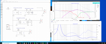
I see what you mean on the mid having lots of ohms, to be honest i didnt even notice i was just adjusting till i got a nice looking frequency curve lol. What happens when i drop the crossed resistor, it actually loses db, then when i drop the in line resistor, it goes back up but gains high and low spots. Ive tried to take better pictures but for some reason it just doesnt want to include the frequencies. The more recent graph starts at 10hz then 100, 200 etc till 1k then increments of 1k after that till 20khz.
Edit - Just taking the resistors off the mid for sec and the frecuency is one big round hump from 1k to 4k and its over 5 db higher than the woofer.
Attachments
Last edited:
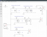
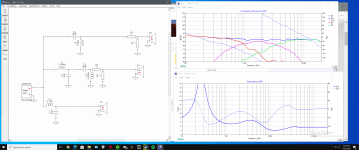
What about something like this?
I started fresh and tried to keep it simple. Also, with Lpads, Is the ohm rating a requirement as in is a 8 ohm Lpad only to be used with a 8 ohm tweeter? Or is the Lpad rating how much resistance it can add?
I started fresh and tried to keep it simple. Also, with Lpads, Is the ohm rating a requirement as in is a 8 ohm Lpad only to be used with a 8 ohm tweeter? Or is the Lpad rating how much resistance it can add?
Attachments
Last edited:
Nope. An 8 ohm L-pad tries to present an 8 ohm load to whatever is driving it. It can only do that if it also has an 8 ohm thing loading it.Also, with Lpads, Is the ohm rating ..
I don't understand your affinity for 2 ohm resistors. Besides presenting too low a load to the filter network, the effect will propagate all the way back to the amp. If you need attenuation, start with a shunt (in parallel with the driver) resistor that matches the driver (providing 3 dB attenuation), then pad it out to 8 ohms with a suitable series resistor. That way the filter will still be seeing a 'standard' load.
Cheers
Last edited:
For L pad you can use calculator: L pad calculator - attenuation dB damping impedance decibel loudspeaker speaker voltage divider - sengpielaudio Sengpiel Berlin
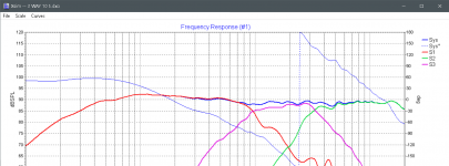
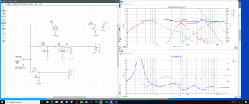
xHavok, I brought up the phase of the individual drivers, shown in the first attachment. We can talk about you working toward bringing them a little more into line.
Also, the scale range is zoomed in more, this is the most you should normally need to see.
With regards to the low impedance, look at the components circled. These are too close to a short circuit, but the single component before each one is also a part of this.
Also, the scale range is zoomed in more, this is the most you should normally need to see.
With regards to the low impedance, look at the components circled. These are too close to a short circuit, but the single component before each one is also a part of this.
Attachments
If im understanding you correctly, i can only use 8 ohm Lpads with 8 ohm drivers, correct? Secondly, im not so much worried about the resistors, im just making sure i can achieve a nice line with L pads, i wasnt planning on buy resistors, just the L pads. Proof of concept maybe? Or am i wrong in thinking that.
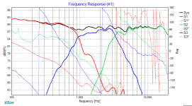
Allen this is where im at currently. Im trying to implement all the advice all at once haha. What do i need to do with the phase?
Stadel, when i do what you told me, the more resistance i add to the resistor in series it makes a bowl shape that just drops db in the middle of the mid's frequency. If i lessen the resistor in series it flattens out but is than louder than the woofer. Am i doing this wrong?
Stadel, when i do what you told me, the more resistance i add to the resistor in series it makes a bowl shape that just drops db in the middle of the mid's frequency. If i lessen the resistor in series it flattens out but is than louder than the woofer. Am i doing this wrong?
Attachments

- Home
- Loudspeakers
- Multi-Way
- DIY Help - 2