Hi All,
I have been trying to pick a balanced output stage design for my active crossover, and I haven't seen a ton of variety. I made up a test board with a 2 op amp Doug Self design using a single LM4562. When I tested it the THD+N was not good. 90db range. With such a simple design and quality opamp, I was expecting to be in the 110's.
When I look at the design, I'm seeing that it calls for 2 100uf capactiors. In order to find such a high value, I used bipolar electrolytics from nichion. Everything else is good quality surface mount components.
Are the caps likely my problem?
Are my expectations unrealstic?
Are there alternatives to electrolytics I should be looking at for such a large cap?
Am I screwing up something else?
Thanks!
I have been trying to pick a balanced output stage design for my active crossover, and I haven't seen a ton of variety.
Yes. Its better to use a fully-differential opamp like OPA1632 or THS4131.
Try measuring the distortion before the output coupling capacitors.
Or, it could be more noise than distortion, depending on the implementation.
It would be good to add an input termination resistor to ground, about 2k-3k.
Or, it could be more noise than distortion, depending on the implementation.
It would be good to add an input termination resistor to ground, about 2k-3k.
Last edited:
Then that means it's more distortion than noise.
Is the loopback distortion much lower than -90dB?
Is the loopback distortion much lower than -90dB?
...When I tested it the THD+N was not good.....
Am I screwing up something else?
Opamp input has no DC reference. Except via the unknown source.
The output caps "can" be removed for testing. In real life they reduce scratchiness in following inputs and protect against some types of disaster. But short out the caps, *check for large DC on the output*, and test. (I suspect the caps are not your problem, if any.)
Attachments
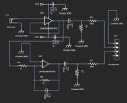
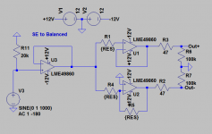
Here is the circuit I created for use with my focusrite 2i2 to convert single ended output to balanced (for input to the 2i2).
Requires an additional opamp (what I breadboarded was using LM4562's) but performance seems good.
Value for RES 10k should be fine. use 0.1% resistors or match well. (I originally used 2.2K, which may give slightly lower noise).
Obviously add some decoupling caps. I'd go with 100nf npos close to the chip pins and 10 or 100uF electros as well.
Tony.
Attachments
Last edited:
Yes.Are my expectations unrealstic?
You CAN NOT HEAR -90dB distortion or noise, even less 110dB so why lose sleep over that?
1k/1k NFB is needlessly loading master and slave Op Amps, think 10k-10k instead
Why the output caps? You don´t really need them and they are potentially the highest distortion generators there.
Be careful about grounding, it´s also a potential distortion generator.
Not because of nonlinearity, but grounding here instead of there may mix signals in an unexpected way.
Not usually a problem, but since we are talking -90dB to -110dB , perspective changes 😎
And of course what PRR said.
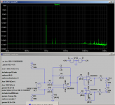
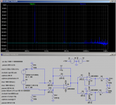
Just checked back over old sims and this was what I came up with to ensure complete isolation of the ground. Along with highly unrealistic performance from the sim 😉 but I would say in the real world it would be lower distortion than I can meausure with my focusrite 2i2. 2nd showing IMD fft.
I can't recall if I breadboarded this variant or not.
One thing I found with my focusrite 2i2 was that the distortion perfomance on the input it was critical to have the ground isolated, which is probably why I came up with the second schematic.
Tony.
I can't recall if I breadboarded this variant or not.
One thing I found with my focusrite 2i2 was that the distortion perfomance on the input it was critical to have the ground isolated, which is probably why I came up with the second schematic.
Tony.
Attachments
Last edited:
- Home
- Source & Line
- Analog Line Level
- Self designed balanced output - running into problems