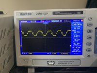
I got this amp and it was stuck in protection, replaced some outputs on the A/B portion of the amp and amp is no longer in protect. However, now the amp is maxing out my 30 amp power supply even though it’s not in protect. I removed the rectifiers for the class D section and amp draws less than a amp of current and produces clean audio on the A/B section. I checked the mosfets for class D no shorts removed driver card and found no faulty components on the board. Pictured below is the drive signal for the gates of the outputs. I wiggled the output indicators and nothing changed as far as current draw. Not sure where the issue is.
Attachments
Hi,
If you removed the rectifiers and the current pull is less than one amp, the problem is on the output section for sure, if it pulls 30a with the rectifiers installed.
Your oscilloscope pwm signal to the gate of the fets does not look very clean.
What is the drive signal which is coming from your pwm chip?
Can you post a photo?
Are you 100% sure your fets are okay? 30a is a lot for not having any shorts on the fets.
Last edited:
I need a schematic or somebody who has repaired one of these before to explain how the class D section of the board works. Specifically how the pwm is generated. It’s very similar to the 3S boards but is slightly different. The photo is of the signal to the output driver pads.
These amps can do strange things.
Was it in the heatsink when you tried to power it up and it drew excessive current?
Was it in the heatsink when you tried to power it up and it drew excessive current?
Try applying remote then removing it and immediately reapplying it (rectifiers in the circuit).
Will it power up after the class D rail caps have charged (by repeated application of remote)?
Will it power up after the class D rail caps have charged (by repeated application of remote)?
Yes it will charge up but when rails get to 18 volts it starts drawing excessive current with rectifiers and outputs in it also creates a ugly square wave on the gates of the outputs. With outputs out it gets 60 volts on rails.
Perry,
I noticed when I connect the base of q4a to pin 1 of u4 for a second after remote engaged and remove the amp will play audio and behave like it should. But as soon as the rail caps discharge it does it again. Are you aware of a solution for this?
I noticed when I connect the base of q4a to pin 1 of u4 for a second after remote engaged and remove the amp will play audio and behave like it should. But as soon as the rail caps discharge it does it again. Are you aware of a solution for this?
I found this on the thread for the 1500 watt version of this amp Memphis MC1.1500. You mentioned something about a fix for the amp but never stated exactly how to perform the fix. U4 is the 5 volt regulator and the its first pin is attached to the secondary ground of the amp.
Well... I think that this could be normal for these amps and isn't an issue when it's powered from a battery that can supply a very short, high current pulse to start the amp.
In one amp, I replaced the IRF640s with IRFB31N20Ds and that solved the 'problem'.
In the first one that I had with this problem (the 1500), I used a jfet, a cap and a resistor to delay the drive but it's a bit of a kluge so I didn't post it.
In one amp, I replaced the IRF640s with IRFB31N20Ds and that solved the 'problem'.
In the first one that I had with this problem (the 1500), I used a jfet, a cap and a resistor to delay the drive but it's a bit of a kluge so I didn't post it.
I replaced the 640’s with IRFB31N20D installed in a vehicle and received the protect light. I looked into using a N-JFET to delay the drivers from turning on but can’t figure out where best to create the circuit.
Did it power up normally on the bench with the 31N20s?
Did the outputs fail after replacing them with the 31N20s?
Did the outputs fail after replacing them with the 31N20s?
No it didn’t power up on the bench and the outputs are still good. If I manually short one of the drivers on the driver board to ground for a second it will oscillate like it should.
OK. This isn't the correct way to repair it. I'll consider it an experiment.
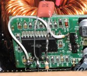
J108
Leg 1 to the base of the drivers.
Leg 2 to ground on the negative regulator
Leg 3 56k (not critical) resistor from the output of the negative regulator
0.1uF cap connected between legs 2 and 3 of the J108.
Sorry about the quality of the images.
J108
Leg 1 to the base of the drivers.
Leg 2 to ground on the negative regulator
Leg 3 56k (not critical) resistor from the output of the negative regulator
0.1uF cap connected between legs 2 and 3 of the J108.
Sorry about the quality of the images.
Attachments

- Home
- General Interest
- Car Audio
- Memphis 16-MC5.1400 Amplifier