Forgive me for asking pedestrian questions. I am new at this. I am reading a lot online and my head is starting to spin. Most of the articles I am finding refer to much lower voltage power supplies that I have here (like 12v arduino things, etc.). I have a powersupply that is giving me roughly 410v with the current transformer and for this project I need to get roughly 265 and 285. Is it a fool's errand to try to split this into two rails either with this or a lower value transformer or should I scrap it and start over. Is there a link or article someone could recommend that addresses putting together the voltage divider circuit in an accessible way and how to determine which resisters and diodes to use?
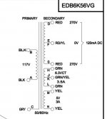
It all depends on how the secondary winding(s) are configured. Do you have a picture or schematic?
How many wires are there on the secondary side?
Jan
How many wires are there on the secondary side?
Jan
Sorry, I misread that you want a pos and neg value, but I realize you just want two different pos values.
That should be no problem.
You could use something that is known as a capacitance multiplier to set the two voltages.
Jan
That should be no problem.
You could use something that is known as a capacitance multiplier to set the two voltages.
Jan
no...he has a 411 v dc supply and he needs two lower voltages in series for the power valves anode and g2 or the rest of the circuit.If the transformer's power is appropriate he could simply use a power series resistor to make the anode voltage lower.
In series? You mean he needs total 560V? I don't think so.
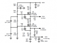
You can simply use two cap multiplier with an additional zener string. Or calculate the resistor values before/after. I need to write an article on that, cap multipliers are very much misunderstood by a lot of people.
Here's an example. The values are of course easily adapted.
Jan
You can simply use two cap multiplier with an additional zener string. Or calculate the resistor values before/after. I need to write an article on that, cap multipliers are very much misunderstood by a lot of people.
Here's an example. The values are of course easily adapted.
Jan
Attachments
Last edited:
If I do the cap multiplier should I look for a transformer with lower vct first? I am not wedded to using this transformer. I just happened to have it.
Did you have the 410V under load? If not, you can expect it to drop, depending on the load. What is your expected load current for the two voltages?
Jan
Jan
Was not under load. THe boards I am trying to power are the ken stapleton phono stage and line stage based on the Marantz circuits. He specifies that they need 285/245 and 285/265 respectively. I have talked to him via email quite a bit and he says it should be no problem to have one rail of 285 and split the difference with the other rail. Not sure how I calculate the total load of the two boards.
Class IX Vacuum Tube Amplification Site Menu
Class IX Vacuum Tube Amplification Site Menu
You could ask him the required current. That's important. You could then load your 410V supply with a resistor to get the same load and see how far it drops.
Jan
Jan
no...i thought he needed an anode voltage for apower valve and it's lower g2 plus phase inverters of the power amp...If it's only phono then he should simply use appropriate series resistors with the load from the 410v supply according to its current needs.Most probably he has enough current .In series? You mean he needs total 560V? I don't think so.
Jan
no...i thought he needed an anode voltage for apower valve and it's lower g2 plus phase inverters of the power amp...If it's only phono then he should simply use appropriate series resistors with the load from the 410v supply according to its current needs.Most probably he has enough current .
Hang on...are you saying it is as simple as...
+---/\/\/\+
|
--/\/\/\/+
?
If so wouldn't I also need diodes in series with each resistor?
![20200927_121043[291].jpg](/community/data/attachments/784/784883-d1fe39f09d955bfb7cfe8123d07c8392.jpg?hash=0f458J2VW_)
- Home
- Amplifiers
- Power Supplies
- Can someone please help me with splitting PS?