Can I make RH84 Amplifier from these parts ?
Hello people
I have few parts as follows.
1) ECC83/12AT7 and EL84 valves
2) One Big transformer as giving supply (350-0-350v)(6.3v)(6V)
3) Two Big Chokes of size around 2.5 inch W x 2.5 inch D x 4 Inch H. Friend who gave it to me says One with Original value of 15H is giving 4H and another 14H one with 10H.
4) Two Small chokes of size around 2 inch x 1 inch (H Value unknown)
5) Two Output transformer with 4 terminal (Probably taps for various impedance) on one side and 3 terminals on other (So probably for pushpull OT) 5K and 7K is written on it with marker pen
My questions are
1) Can I use 350-0-350v PT for RH84's EL84 Valve ? recommended voltage is 315V
2) Original RH84 Schematic shows 10H100mA Choke in PS. Can I use two in series that I already have (4H+10H) so as to give more filtering ?
2) As suggested by Audiowize in another thread. Using small chokes between rectifier and Capacitors will reduce some voltage. Correct ?
3) Can I use (pushpull OT) that I have just to check the output and sound testing purpose ? will buy single ended OT later if all OK.
tell me how to go about this with parts I have.
thanks and regards
Last edited:
1) With a choke input filter you would come close to (a little over) 315 V, with a capacitor input filter you would wind up way to high (about 430 V). If you would use a choke input filter and solid state rectifiers, the voltage will be around 430 V during the time the tubes warm up. Only when they conduct enough current, the voltage will drop (only than the choke 'works' to drop the voltage). So your capacitors have to be able to withstand these voltages.
2) I don't know if one of your chokes (the 10 H would be the most likely candidate) can serve as the input choke (also called: swinging choke).
3) I don't know if they can stand enough current.
4) I would not advise that. Push-pull output transformers don't have an airgap (because the don't need to since the dc-currents from the centre-tap to the two anode connections cancel eachother out so the core doesn't get saturated). Single ended output transformers do have an airgap (they need one to be able to pass the dc-current without getting saturated).
Last edited:
Hi,
have been reading about articles related to tube amps. Specially nice ESP Website .
As this is learning/fun/BuildWithPartsInHands project 🙂 I have narrowed down my choices for transformer.
1) Custom make 222-0-222V Transformer for B+ supply and use SS rectifier, Caps, resistors. (This will cost money)
2) Rewind existing transformer to reduce necessary voltages. (Will cost less money)
3) Use SS Rectifier and 10H Choke (Choke is big and heavy and seems will stand enough current) (least expensive)
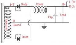
My question is if I use SS Rectifier and 10H choke as mentioned in Fig. 5 of above ESP article...
- What wattage should I use for 3k6 resistor shown ? (Already have 5W different value resistors from my Valve radio repair work)
- Can i modify capacitors value to bring down/up precise voltages requirement of more or less 315V?
- Which rectifier Diodes to use ?
--------------------------------------------------------------------
- If I make custom 222-0-222v transformer what VA should I aim for ? (Heater transformer will be separate as I also have couple of them)
thanks and regards.
have been reading about articles related to tube amps. Specially nice ESP Website .
As this is learning/fun/BuildWithPartsInHands project 🙂 I have narrowed down my choices for transformer.
1) Custom make 222-0-222V Transformer for B+ supply and use SS rectifier, Caps, resistors. (This will cost money)
2) Rewind existing transformer to reduce necessary voltages. (Will cost less money)
3) Use SS Rectifier and 10H Choke (Choke is big and heavy and seems will stand enough current) (least expensive)
My question is if I use SS Rectifier and 10H choke as mentioned in Fig. 5 of above ESP article...
- What wattage should I use for 3k6 resistor shown ? (Already have 5W different value resistors from my Valve radio repair work)
- Can i modify capacitors value to bring down/up precise voltages requirement of more or less 315V?
- Which rectifier Diodes to use ?
--------------------------------------------------------------------
- If I make custom 222-0-222v transformer what VA should I aim for ? (Heater transformer will be separate as I also have couple of them)
thanks and regards.
1) To get the recommended 315 V, a 222-0-222 V secondary is way too low (you wind up with about like 250 V). You should use something like 275-0-275 V. This is a pretty standard value so you don't have to have it made custom. Look for other schematics with 2 x EL84 push-pull (with SS rectification) and note down which power transformers are being used. Than buy one of them 'of the shelve'.
2) I would never do that, but it's up to you ofcourse.
3) Possible, but option 1) looks easiest/safest to me.
- The 3K6 resistor in the diagram represents the load (which draws about 100 mA), so it's not a 'real' resistor.
- A little but in my opinion this is not the way to deal with too high a voltage.
- If you go for option 1) or 2) 2 x 1N4007 is fine. If you would go for option 3) I would use 8 x 1N4007 (pairs of two in series) to be absolutely shure. I would shunt every 1N4007 with a capacitor of 0.01 uF (1000 V) to supress the switching noise of the 1N4007's.
Thanks PCL200.
I thought Option (1) CRC type power from 222-0-222v will give me 315V (approx. multiplication of 1.4) ?
Will be testing parts that I already have with extreme precaution. (Series bulb and careful protection, One hand at back, rubber slippers. PT and stuff on wooden board, Double check everything than turn power on)
Will power supply testing of 350-0-350V <> Rectifier(as mentioned) <> Choke <> Cap... require any load to test the output voltage ? Or just measure the volts of open leads by multimeter ? How much voltage sag I can expect for this amplifier when loaded with circuit. Rough approximation.
Thanks and hope I am not making fool of myself by asking simple questions.
Regards
The "1.4" is the theoretical multiplier, because it doesn't take into account the resistance in the windings of the transformer. Look on the internet for schematics with 2 x EL84 push-pull and SS rectification and you will see that the power transformers used in them are rated much higher than 222-0-222V.
You will have to measure with a (artifical) load, else the choke can't do it's 'swinging' with the result that the voltage will be way higher than with a (artificial) load (something like 550 V). It has to be a beefy resistor (or you have to connect several resistors in series and/or parallel). The current through the artificial load in figure 5 on the site you linked to will be I = V / R = 370 / 3600 = 103 mA. The dissipation in the artificial load will be P = I x V = 0,103 x 370 = 38 Watt. To be on the safe side, I would go for a resistor which is rated for at least 50 Watt. If for instance you connect three resistors of 1200 in series, you also get the 3600 Ohm. Each resistor of 1200 than has to be rated for at least 17 Watt.
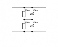
With these high voltages, you have to use electrolytic capacitors with high enough voltage. I would go for two 450 V capacitors in series (the capacitance than halves, so 2 x 100 uF in series will give 50 uF in total) and with a 220K resistor shunting each capacitor (this will distribute the total voltage equaly over the two capacitors).
You will have to measure with a (artifical) load, else the choke can't do it's 'swinging' with the result that the voltage will be way higher than with a (artificial) load (something like 550 V). It has to be a beefy resistor (or you have to connect several resistors in series and/or parallel). The current through the artificial load in figure 5 on the site you linked to will be I = V / R = 370 / 3600 = 103 mA. The dissipation in the artificial load will be P = I x V = 0,103 x 370 = 38 Watt. To be on the safe side, I would go for a resistor which is rated for at least 50 Watt. If for instance you connect three resistors of 1200 in series, you also get the 3600 Ohm. Each resistor of 1200 than has to be rated for at least 17 Watt.
With these high voltages, you have to use electrolytic capacitors with high enough voltage. I would go for two 450 V capacitors in series (the capacitance than halves, so 2 x 100 uF in series will give 50 uF in total) and with a 220K resistor shunting each capacitor (this will distribute the total voltage equaly over the two capacitors).
OK I get it what you mean. I do have high wattage (Vintage Fan Regulator) Resistor. But let me think/read about all aspects then cautiously will proceed.
regards,
regards,
Hi,
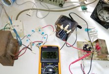
Did the test as mentioned. 1000V caps were not available so used 6x0.01 2kVA and 2x0.001 2kva caps. Used 6x470 ohms 10W plus 1x600ohms ~40W(Fan regulator) resistors in series as load. Connections was as follows.
AC Mains-Series bulb supply to Primary--Secondary supply to Rectifier Bridge (2xIN4007 in series with cap parallel to each diode)--B+ Voltage to unknown value Choke.--Dummy load--Fan on Resistors.
First I got low voltage so presumed the series bulb was drawing voltage. So after few minutes. Removed the series test bulb and measured voltages as follows.
Voltages at Primary (233v AC)
Voltages at Secondary (380v AC)
Voltages at Rectifier (337v DC)
Voltages at Load (326v DC)
Before the testing I measured voltage whole day on my AC Mains It varied from 235 to max. 245 V.
So..
1) Am I good to go with regards to power supply for RH84 amp ?
2) With voltage fluctuations on my AC Mains I expect output (326v at load ) to increase 3% so I will be getting around max. 342V. Is it safe for Valves ?
3) Transformer also has 2 pair wire (2mm thick) for filament supply and output is 7.2 and 6V. I plan to use One AC supply to filaments of EL84 parallel. And separate transformer (Regulated DC) for 12AT7/ECC81 filament. Will that be OK ?
here is the ugly picture of my test.😱
Thanks very much for helping me.
Attachments
1) and 2): The voltage looks fine to me (326 V + 3 % = 336 V) to start with. It's pretty easy to get rid of the little surplus with a resistor + extra decoupling/filter capacitor. The tubes are running in class A so the extra resistance doesn't influence the performance of the amplifier. Looking at the size of your transformer, I think it will have (just) enough current capability for 2 x EL84 at a B+ of 315 V, but ofcourse I can't garantee this. Did you feel/notice any heating of the transformer when measuring with the load?
3): Does it say "7.2 V" and "6 V" on your transformer or did you measure it? And if you measured it, did you measure it with or without a load? If not, could you measure them with a loadresistor of 6.8 Ohm or a bit higher (both at least 10 Watt, or else combine some more resistors to get there)?
I don't think the 7.2 V gives enough input voltage after rectification for a voltage regulator. But it would be enough for a bridge rectifier an a C-R-C filter.
At these input levels (about 1 V) I don't think dc-heating of the 12AT7/ECC81 is necessary, but hey, if you can than why not.
Last edited:
Sorry missed the important part. (1) My transformer is center tapped dual voltage. For the time being testing purpose I used center tap lead as ground and one lead for positive supply. (2) Also from transfomer EI core center piece laminate which is roughly 1.5 inches X 1.5 inches gives me rough estimation of little more than 150VA. Would that be enough for stereo ? (3) The filament supply was tested with out any load on them. If I can connect them in series and than regulate and filter them and lower voltages to 6.3. Atleast they can be used somewhere (EL84 or 12AT7). I am also OK to not use them.
An out of the box idea ?
Having tested with series bulb at the beginning of the test I used to get low voltage so now I am thinking can I place tiny 250 V bulb at mains input (which will also serve as Amplifier ON indicator with a thermistor in series.) A tiny heatsink will be put deliberately on thermistor so it reaches its critical maximum temperature slowly (would serve as soft start).
This way I get little bit of Soft start + Power on Indicator + loose couple of volts* ?
Any robust low noise rectifier diode so I can avoid caps and diodes in series ? But if you say they are necessary I am ok with it. Probably they are also helping little bit in voltage reduction. right ?
* reducing couple of volts will help me if I get occasional overvoltage on my Mains supply.
addition : sorry one more question. What if I put regulator after rectifier (for B+) this will also reduce volts ?
thanks.
Last edited:
I think I made a mistake in post # 5 by writing about 8 x 1N4007, so about a bridge rectifier. My apologies.
To prevent more mistakes: So now you have a bridge rectifier over one half of the HV secondary of the 350-0-350V transformer? And this gives 326 V with a choke input filter over the artifical load?
What I advise you to try now, is just using two pairs of 1N4007's in a full-wave rectifier circuit (so with the centre-tap connected to ground) with the choke input filter and the artificial load.
150 VA would be more than enough for your amplifier, but I didn't check your calculation (deducting the wattage from the sizes). The B+ for both the channels will be about 0.1 x 350 = 35 Watt, and the filament power will be about 1.8 x 6.3 = 11.4 Watt.
It is realy not necessary to feed the filaments of the EL84's with dc. When we know what the voltages of the filament windings are with a load, it's easier to decide what to do. Maybe you could just feed the EL84's with 6.3 Vac and the 12AT7 with 6.3 Vdc using just a bridge rectifier and C-R-C (or if the voltage is not high enough: just a C).
If you reduce the voltage at the primary of the power transformer, you will lower all secondary voltages, so also the voltages for the filaments. Again: Lowering the B+ with just a resistor, an by doing so getting extra filtering (with a C after the resistor) is perfectly fine. I don't see the point of complicating things with a bulb at the primary.
You are right. I Will discard complications and go for simple things.
Clean slate :
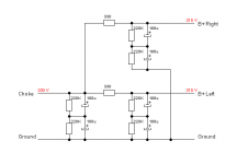
Since I now have a working suitable transformer and nice choke and I am almost getting required B+ for RH84 amp. I will do fresh testing with center tap connection. Kindly see attached schematic. Is it OK ? Can I use same IN4007 and Capacitor in series with previously tested load of 6x470 and 1x600 ohms series resistors. Will also add more caps. if it reduces voltage and does more filtering. But tell me which values and where.
thanks and very much appreciated your help.
Clean slate :
Since I now have a working suitable transformer and nice choke and I am almost getting required B+ for RH84 amp. I will do fresh testing with center tap connection. Kindly see attached schematic. Is it OK ? Can I use same IN4007 and Capacitor in series with previously tested load of 6x470 and 1x600 ohms series resistors. Will also add more caps. if it reduces voltage and does more filtering. But tell me which values and where.
thanks and very much appreciated your help.
Attachments
See the last part of post #7. So pick two capacitors of 100 uF (400 V or higher). But this value is not critical for testing; 2 x 50, 2 x 47, 2 x 33 or even 2 x 22 uF will do also. In the real amplifier I would not go lower than 2 x 100 uF.
If a further resistor (or even better: two resistors, so one per channel), followed by a (again) two capacitors in series to ground, is necessary/possible depends ofcourse on the outcome of your measurements.
Addition: Replace Cap in your schematic by this:
If a further resistor (or even better: two resistors, so one per channel), followed by a (again) two capacitors in series to ground, is necessary/possible depends ofcourse on the outcome of your measurements.
Addition: Replace Cap in your schematic by this:
Attachments
Last edited:
Let's calculate this very 'safely'.
Suppose there appears 500 V over the two 220K resistors in series. The current running through them than is: I = V / R = 500 / 440000 = 1.14 mA. The dissipation for one 220K resistor than is: P = I x V = 0.00114 x 250 V = 0.284 Watt (V = 250 V because the 500 V divides equally over the two resistors).
So even 1/2 Watt resistors would do. But I would still choose them 1 or even 2 Watt. I don't like little tiny resistors with these voltages over them.
Hello
I did the tests again. And put in 220k resistors as mentioned. Voltages I am getting are
primary (238v)
Secondary (395v)
at Bridge (350v)
at Load (330v)
after above measurements I did put in extra diode||capacitor in series; but it didn't result in any voltage reduction at load. i.e. the voltage remained same 330v.
Original requirement as per schematic is 315v.
1) after loading with actual circuit will this 330v drop ?
2) At 238v AC mains I am getting 330v (after rectification and filter). Sometimes my AC mains supply is 245v. so probably this will increase 330v a little bit. What can we do about it ? Or is it OK for EL84 valve ?
3) Any simple trick to still reduce B+ ? Resistors ? High Voltage regulator IC ? Thermistor at Secondary ?
4) Suppose I use 2 supplies of filament (Not shared with HV windings). It will put tiny little stress on shared EI core? Will that help in miniscule way?
thanks 🙂
OK, perfect. You can use the 15 V surplus to seperate the channels a bit.
So one channel draws about 45 mA. We have to loose 15 V. So the extra R per channel has to b: R = V / I = 15 / 0.045 = 333 Ohm, so the standard value 330 Ohm will do fine. The resistor will dissipate: P = I x V = 0.045 x 15 = 0.675 Watt so 1 Watt will do (but I would go for 2 Watt).
The schematic after the choke, could be like this:
Addition: Don't worry about the mains voltage changing a bit. Tubes were made to take some extra on top of their maximum ratings. Mains voltages probably changed a lot more in the old days so tubes were designed to take these changes.
Attachments
Last edited:
Ok. will do that. Happy that my amp is progressing. You have been a great help. Thanks so much. Will procure the parts tomorrow.
1) 'separate the channel a bit' This will help by having more impedance between channels ? Channel bleed ? or improves the smoothing of supply ?
2) As in the schematic in your last post. Extra filtering is nice I suppose. But will it add harmonics ? As mentioned in ESP link here in '6.Choke input filter' section.
sorry for newbie questions. just learning this things. 😱
1) It seperates because the two channels don't directly share one capacitor anymore, and it makes the ripple on the B+ lower.
2) I scanned the page you linked to. As far as I understand it correctly, the parts about harmonics are about the comparison between choke input (like yours) and capacitor input. The choke input would do better. Maybe you think that adding a resistor and capacitance like I suggested would 'waist' the advantage of the choke input. My knowledge is not good/deep enough to be sure, but I think there's no waist. I doubt that I could here a difference, if any. And the extra filtering (lower ripple) looks like a good trade-off anyway.
2) I scanned the page you linked to. As far as I understand it correctly, the parts about harmonics are about the comparison between choke input (like yours) and capacitor input. The choke input would do better. Maybe you think that adding a resistor and capacitance like I suggested would 'waist' the advantage of the choke input. My knowledge is not good/deep enough to be sure, but I think there's no waist. I doubt that I could here a difference, if any. And the extra filtering (lower ripple) looks like a good trade-off anyway.
- Home
- Amplifiers
- Tubes / Valves
- Can I make RH84 from these parts ?