Hey folks. This is a followup to another post https://www.diyaudio.com/forums/tubes-valves/359369-amp-design-critique.html
I made a couple of adjustments to the schematic and breadboarded a prototype. It's working okay for the most part, but now I have this very low frequency ringing. Originally I thought it was motorboating, I was pulling down the PSU too hard with how I biased the KT88, but I bumped the resistor up and, while it became "better", it hasn't entirely gone away.
Here's my current schematic(sort of, will explain later)

Now the ringing isn't completely audible as before, but I can still see it on the scope and on the woofer cone. It's around 7.7Hz, and the amplitude gets much greater than this.

I think it's a ring, not an oscillation, because it's not always there and seems to get "triggered", especially during bassier parts, and after a few seconds seems to resolve without any intervention(other than the song moving on).
I'm almost completely positive that this is coming through my global feedback and back through the signal chain. It completely goes away when there is no feedback at all. The schematic has R6 as 1k, but in actuality I have a 30k in there. At this little feedback, I'm not getting the kind of frequency response that I want, but I can't make it much lower without increasing the chance of ringing.
LTSpice is even showing a large phase shift at sub-10Hz frequencies(not exactly 7.7Hz). I'm still an amateur and I'm not sure how to address this. Is this a common problem and is there a specific resource I can be pointed to to understand it better?
Thanks
I made a couple of adjustments to the schematic and breadboarded a prototype. It's working okay for the most part, but now I have this very low frequency ringing. Originally I thought it was motorboating, I was pulling down the PSU too hard with how I biased the KT88, but I bumped the resistor up and, while it became "better", it hasn't entirely gone away.
Here's my current schematic(sort of, will explain later)
Now the ringing isn't completely audible as before, but I can still see it on the scope and on the woofer cone. It's around 7.7Hz, and the amplitude gets much greater than this.
I think it's a ring, not an oscillation, because it's not always there and seems to get "triggered", especially during bassier parts, and after a few seconds seems to resolve without any intervention(other than the song moving on).
I'm almost completely positive that this is coming through my global feedback and back through the signal chain. It completely goes away when there is no feedback at all. The schematic has R6 as 1k, but in actuality I have a 30k in there. At this little feedback, I'm not getting the kind of frequency response that I want, but I can't make it much lower without increasing the chance of ringing.
LTSpice is even showing a large phase shift at sub-10Hz frequencies(not exactly 7.7Hz). I'm still an amateur and I'm not sure how to address this. Is this a common problem and is there a specific resource I can be pointed to to understand it better?
Thanks
It could still be motorboating. Only if the internal resistance of your power supply is very low, you can get away with running three stages without decoupling of the B+ between stages.
Probably unrelated to your problem: Is Va of the 12AU7A 300 Vdc or lower (300 Vdc is the maximum value for the 12AU7A)?
Probably unrelated to your problem: Is Va of the 12AU7A 300 Vdc or lower (300 Vdc is the maximum value for the 12AU7A)?
It could still be motorboating. Only if the internal resistance of your power supply is very low, you can get away with running three stages without decoupling of the B+ between stages.
Probably unrelated to your problem: Is Va of the 12AU7A 300 Vdc or lower (300 Vdc is the maximum value for the 12AU7A)?
Agree it could still be the PSU(I'm waiting for more caps to come in to decouple the stages). My thinking was that, if I remove the feedback loop, I'm using more power than with it... yet the problem goes away. It seems the more feedback(less overall gain) the more susceptible this is to ringing. If it were PSU/motorboat related, shouldn't I expect the opposite?
Regarding the 12AU7, it's running at about 290V warmed up, cutting it close, I'll address that, good find.
i'd run a 10 megohm resistor from U2 anode to u3 grid before or after the 3k resistor...
Could you explain? 10M seems high for local feedback so I'm curious what your thinking is. I'll give it a try. Can't hurt!
Thanks.
it's not local feedback,it is global feedback taken before the transformer...you could change that value to a smaller one like 4.7megohm...it should make clear if it's a motorboating or smth else as it will work especially at low frequencies.
it's not local feedback,it is global feedback taken before the transformer...you could change that value to a smaller one like 4.7megohm...it should make clear if it's a motorboating or smth else as it will work especially at low frequencies.
You're right, I misread what you said. To be clear, you're suggesting get rid of R6 and do this instead, get the OT out of the picture?
no not at all....just have two different feedback to make clear what's the problem.If it's motorboating you just need to make sure you have a phased mild feedback at low frequency.
I also have a feeling that c2 and c4 is too big too allowing to a greater content of very low frequencies to get into the transformer .22...47nf should be absolutely ok there.
I also have a feeling that c2 and c4 is too big too allowing to a greater content of very low frequencies to get into the transformer .22...47nf should be absolutely ok there.
With the type of feedback dreamth suggests, what will happen if the source has no dc-path to ground? Or if no source is connected? Wouldn't the voltage on the anode of the KT88 than divide over the 10 Meg feedback resistor and the 1 Meg grid resistor of the 12AX7A, resulting in a grid voltage of some 45 V at no signal?
no not at all....just have two different feedback to make clear what's the problem.If it's motorboating you just need to make sure you have a phased mild feedback at low frequency.
I also have a feeling that c2 and c4 is too big too allowing to a greater content of very low frequencies to get into the transformer .22...47nf should be absolutely ok there.
Okay, I gave it a shot. A couple of things... I do still see a little instability on the scope, but it's not nearly as severe and it's not periodic(I can't measure out exactly 7.69Hz like I did last time, or see the woofers move, it's all over the place but slight nudges). The bass itself is now severely attenuated(at least by ear) with 10M on there.
i suggested that for a first simple check.he can use a series capacitor with that 10 meg resistor if the case. i suspect that the coupling capacitors are way too high...making them lower in value might cure that ringing.try 5 megohm too....it may go as low as 1 megohm Schade feedback resistor
Last edited:
Well, than the source you are using must have a low impedance, and no dc-blocking...
Did you measure the grid voltage of the 12AX7A?
Did you measure the grid voltage of the 12AX7A?
With the type of feedback dreamth suggests, what will happen if the source has no dc-path to ground? Or if no source is connected? Wouldn't the voltage on the anode of the KT88 than divide over the 10 Meg feedback resistor and the 1 Meg grid resistor of the 12AX7A, resulting in a grid voltage of some 45 V at no signal?
Yep, you're right. I'm sure the 12AX7 wasn't happy about that. I didn't run it long and it still works.
I actually have another coupling cap on the input before the first 3k.
try lowering the 220nf capacitors to 10...22nf .that might be the cause for that ringing.you can make the bias resistor much lower like 100k or even 10 k if you use dc feedback.
Last edited:
Well, than the source you are using must have a low impedance, and no dc-blocking...
I think the PSU I have for this prototype is overkill as it is. Unfortunately I just scribbled this on piece of paper that is now lost. Basically just a simple CLC (10uF, 10H, 200uF). When I add another channel we will have to see 😎
try lowering the 220nf capacitors to 10...22nf .that might be the cause for that ringing.you can make the bias resistor much lower like 100k or even 10 k if you use dc feedback.
I had originally thought of this(essentially making a highpass via the coupling caps), but in the books I was recommended here(Blencowe and Jones) they were cautioning against doing this, as it may just be putting a bandaid on the real underlying problem.
I appreciate both of your input! Going to give both a shot when the parts come in.
you could try with any quality capacitors at hand...at least on one channel to see what happens.if you don't have capacitors,use two in series by moving the capacitors from one channel to the one you're testing.You'd have 110nf instead of 220nf...
With 'source' I meant whatever you are using to generate input voltage (CD-player, tone generator, etc.).
But since you are using a capacitor between the source and the grid of the 12AX7A, there is no dc-path to the source. Your results from post #10, and your confirmation of the high grid voltage in #post 13 leave me a bit puzzled.
But since you are using a capacitor between the source and the grid of the 12AX7A, there is no dc-path to the source. Your results from post #10, and your confirmation of the high grid voltage in #post 13 leave me a bit puzzled.
you could try with any quality capacitors at hand...at least on one channel to see what happens.if you don't have capacitors,use two in series by moving the capacitors from one channel to the one you're testing.You'd have 110nf instead of 220nf...
Sadly I am new at this and don't really have an arsenal of caps to try, and order as needed. I couldn't easily find a good high voltage(600V) polypropylene kit, but if you know where I can get one(instead of buying a bunch of random stuff) I'm all ears!
With 'source' I meant whatever you are using to generate input voltage (CD-player, tone generator, etc.).
But since you are using a capacitor between the source and the grid of the 12AX7A, there is no dc-path to the source. Your results from post #10, and your confirmation of the high grid voltage in #post 13 leave me a bit puzzled.
It's an iPhone, but you're right, behind the cap it's moot.
This didn't make sense to me either, so I went back and measured again. I was actually reading a bias of -48mV, not V, my multimeter screen is small.
I checked that the 10M is dropping 468V, the 1M is dropping 2.5V, and the grid stop 3k(the 10M is hooked up at the 1M) is dropping 130mV, so basically it seems like 43uA(most of it) is going through the grid via R15. Cathode is probably not happy, but I bought a bunch of cheapo 12AX7s with the expectation I'm probably going to ruin at least one 🙂 Still works for now.
It looks to me like the circuit is not rolling off the LF gain sufficiently before the output transformer filter response kicks in. All your high pass filters in the circuit are set at very low frequencies (<5Hz), so none of them is likely to be sufficiently lowering the LF gain before the output transformer response kicks in, and the phase shifts of each could be all adding to the issue. Have you measured what level of global feedback is being applied?
Given you want to retain the output transformer, then typically you would either remove a high pass filter (ie. make the first and second stages DC coupled), or raise one or all circuit based high-pass filter frequencies (C4-R3; C2-R2; C1-R11).
Given you want to retain the output transformer, then typically you would either remove a high pass filter (ie. make the first and second stages DC coupled), or raise one or all circuit based high-pass filter frequencies (C4-R3; C2-R2; C1-R11).
It could still be motorboating. Only if the internal resistance of your power supply is very low, you can get away with running three stages without decoupling of the B+ between stages.
Alright, you guys win. While I'm waiting for more components, I threw my PSU design(as is) into LTSpice to see what would happen to B+ when applied to my circuit.
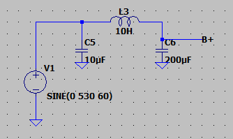
The results were unquestionably familiar.
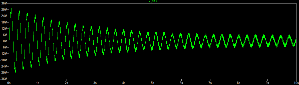
The frequency was about half, but simulated vs real life, that's close enough for me. Thanks for steering me back. I probably would have wasted a lot of time in denial otherwise.
- Home
- Amplifiers
- Tubes / Valves
- Very low frequency ringing