I have been testing my Tubelab SSE and am trying to figure out the best way to ground everything. It is wired in triode mode with no CFB. Initially I tried to follow George's wiring diagrams but was hearing some hum through the speakers. I then tried some variations and came upon what I think is the quietest. You can see my questions in the Tubelab forum here.
I was not getting any response in that forum so thought I would try here. Please see attached for a drawing of how I am grounding the amp currently. The power inlet and toroidal ground straight to the chassis through the PCB mount. The soft start board, PCB, and speaker out common ground to a single point that is attached to the chassis ground with a CL60. The chassis is aluminum top, front, back, bottom with wood sides.
My first concern is that what I did is safe. Second is there a better way I should be approaching this. Thanks for any suggestions.
Attachments
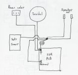
The power inlet ground should go to a point on the chassis near to the inlet, and if the chassis is separate metal parts, they may need to be linked.
Not sure what role the CL60 plays? It it an NTC, but no current should be flowing through it.
Were you intending to fit the supplementary motor run capacitor?
Otherwise I recommend the Tubelab site, which has a connection diagram that I followed.
Not sure what role the CL60 plays? It it an NTC, but no current should be flowing through it.
Were you intending to fit the supplementary motor run capacitor?
Otherwise I recommend the Tubelab site, which has a connection diagram that I followed.
The only current flowing through it will be the result of impedance differences between the circuit earth and the steel chassis earth .
The NTC value (nominal ) is 10 ohms which does present the standard earth "isolation " value of an input earth and an output earth as this seems to apply to the soft start circuit /loudspeakers earth return ( to chassis ) where there is a direct connection to mains earth and transformer it looks like some safety measure ( for the amplifier circuit ) in the event of a fault condition from the mains as there would need to be sufficient current to heat the NTC and change its resistance value.
The NTC value (nominal ) is 10 ohms which does present the standard earth "isolation " value of an input earth and an output earth as this seems to apply to the soft start circuit /loudspeakers earth return ( to chassis ) where there is a direct connection to mains earth and transformer it looks like some safety measure ( for the amplifier circuit ) in the event of a fault condition from the mains as there would need to be sufficient current to heat the NTC and change its resistance value.
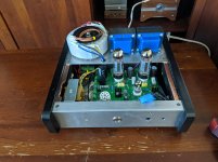
I do have a motor run cap under the top plate, that and the inductor are bolted to the bottom plate. I also have copper tape running along all the wood mounting surfaces to make sure the aluminum panels are grounded.
Looking at the wiring diagrams on the Tubelab site I could not find my exact layout. I have 2 rca inputs going to a selector switch then a volume control which splits between the pcb and subwoofer out. Because I was unsure about grounding to a single rca I used one of the other ground points on the pcb that George mentions in the wiring diagram. I also have the toroidal and soft start board to ground. The CL60 idea came from the maker of the soft start board as a recommendation when using it. I believe it functions just as duncan 2 explained.
Looking at the wiring diagrams on the Tubelab site I could not find my exact layout. I have 2 rca inputs going to a selector switch then a volume control which splits between the pcb and subwoofer out. Because I was unsure about grounding to a single rca I used one of the other ground points on the pcb that George mentions in the wiring diagram. I also have the toroidal and soft start board to ground. The CL60 idea came from the maker of the soft start board as a recommendation when using it. I believe it functions just as duncan 2 explained.