I hope that this is not too ridiculous of a post. I’m just getting to the stage of thinking I know enough to be dangerous.
I’ve just built an F5 amp and am now starting to upgrade the upstream components. First on the agenda is a Raspberry Pi based streamer with a separate DAC HAT, most likely an Allo Boss. I currently trying to decide how to power this setup. There are obviously a lot of power supplies available, but since I’ve got some time on my hands, I thought I would try to build one.
I’ve gone through a lot of threads regarding DAC power supplies and tried to distill the data / opinions as much as possible. With regards to power supply noise, it seems like “low noise” is good, but “ultra-low noise” may not make much of a difference practically. This seems reasonable given that the DAC has filters to further reduce power supply noise and the RPi creates enough noise internally to overwhelm any from the power supply.
In the thread on the Shanti Power Supply, there was a lot of discussion on load transients and having a significant amount of capacitance at the output to deal with these transients. The prevailing opinion seemed to be that this had an impact on both measurements and perceived audio quality.
Putting that together, I’m thinking about building the attached circuit. The basic design ideas were:
• Single Rectifier into a reasonable capacitor bank (3000uF) to drop ripple somewhat and keep supply voltage above the dropout of the succeeding regulators.
• Separated regulator / filter circuits for RPi and DAC fed by the single unregulated supply.
• 7805 regulator with the datasheet implementation of the high current regulator with overload protection. This should provide more than enough power for the device and the overload protection will limit the inrush current when charging the succeeding capacitor bank.
• A lot of capacitance on the output of the regulator, both for bulk storage and decoupling. The capacitor bank will include one 1F supercapacitor (581-SCMR22G105SRBA0), 2000uF of Electrolytics and 10uF, 1uF, and 0.1uF decoupling caps.
I’ve got a couple of questions before I tackle the build and was hoping to get some input.
• I realize that over 1F of capacitance at the output is crazy, but has it passed crazy and transitioned into stupid? The supercapacitor costs ~$5, so it’s not going to impact cost too much as long as it won’t have any negative effects on power quality.
• Is the balance / amount of electrolytics about right?
• Is there something else that I’m completely missing?
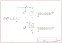
I’ve attached a schematic of my idea. Any input is appreciated.
I’ve just built an F5 amp and am now starting to upgrade the upstream components. First on the agenda is a Raspberry Pi based streamer with a separate DAC HAT, most likely an Allo Boss. I currently trying to decide how to power this setup. There are obviously a lot of power supplies available, but since I’ve got some time on my hands, I thought I would try to build one.
I’ve gone through a lot of threads regarding DAC power supplies and tried to distill the data / opinions as much as possible. With regards to power supply noise, it seems like “low noise” is good, but “ultra-low noise” may not make much of a difference practically. This seems reasonable given that the DAC has filters to further reduce power supply noise and the RPi creates enough noise internally to overwhelm any from the power supply.
In the thread on the Shanti Power Supply, there was a lot of discussion on load transients and having a significant amount of capacitance at the output to deal with these transients. The prevailing opinion seemed to be that this had an impact on both measurements and perceived audio quality.
Putting that together, I’m thinking about building the attached circuit. The basic design ideas were:
• Single Rectifier into a reasonable capacitor bank (3000uF) to drop ripple somewhat and keep supply voltage above the dropout of the succeeding regulators.
• Separated regulator / filter circuits for RPi and DAC fed by the single unregulated supply.
• 7805 regulator with the datasheet implementation of the high current regulator with overload protection. This should provide more than enough power for the device and the overload protection will limit the inrush current when charging the succeeding capacitor bank.
• A lot of capacitance on the output of the regulator, both for bulk storage and decoupling. The capacitor bank will include one 1F supercapacitor (581-SCMR22G105SRBA0), 2000uF of Electrolytics and 10uF, 1uF, and 0.1uF decoupling caps.
I’ve got a couple of questions before I tackle the build and was hoping to get some input.
• I realize that over 1F of capacitance at the output is crazy, but has it passed crazy and transitioned into stupid? The supercapacitor costs ~$5, so it’s not going to impact cost too much as long as it won’t have any negative effects on power quality.
• Is the balance / amount of electrolytics about right?
• Is there something else that I’m completely missing?
I’ve attached a schematic of my idea. Any input is appreciated.
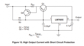
> 7805 regulator with the datasheet implementation of the high current regulator with overload protection.
Your drawing did not make sense to me. I hunted-down the appnotes, and there are several differences, and they look like no-go differences to me.
Your drawing did not make sense to me. I hunted-down the appnotes, and there are several differences, and they look like no-go differences to me.
Attachments
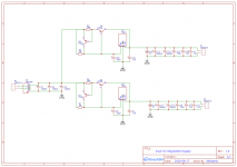
Thanks. I went back and corrected the errors.
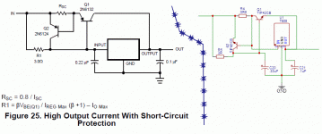
With the 7805, every manufacturer has some slight variations in the circuits they present. I should have been more specific that I had used the one from the Fairchild datasheet. It is generally the same, but does specify different transistors and capacitance values. I've attached the snippet of the datasheet from Fairchild.
With the 7805, every manufacturer has some slight variations in the circuits they present. I should have been more specific that I had used the one from the Fairchild datasheet. It is generally the same, but does specify different transistors and capacitance values. I've attached the snippet of the datasheet from Fairchild.
Attachments
Much more than adequate capacitance (typically around 10uF) will make the regulator response very sluggish.
It would also likely fold-back current limit into the load, and the output capacitor may not charge up at all.
What would happen to the F5 if you attach that big capacitor to its output?
Same thing for the regulator, which is also a feedback amplifier.
It would also likely fold-back current limit into the load, and the output capacitor may not charge up at all.
What would happen to the F5 if you attach that big capacitor to its output?
Same thing for the regulator, which is also a feedback amplifier.
Last edited:
The sluggishness of the response makes sense. For a given load, you will have a smaller amplitude dip, but the duration will be longer. This would bring up the question of whether the RPi and DAC would typically perform better with a larger but shorter dip, a smaller but longer dip, or some "sweet spot" that is a tradeoff of both. If you believe the measurements and listening tests from the thread I mentioned on the Shanti PS, it seems to indicate that having quite a bit of capacitance on the output is better. What I haven't seen addressed is whether this is a "sweet spot" in capacitance or is just the point that they felt comfortable with diminishing returns. We have quite obviously reached a point of diminishing returns, but I can't find any info to point to a decrease in performance with extra capacitance.
I'm not terribly worried about the startup time given that it will be powered 24/7 for a streaming audio player. With a 3A current limit, we would be around 10s for a full charge (5T). That's not a deal breaker at all. However if it does fold back, that would be a problem. The additional circuit added around the 7805 does not have a foldback, but I haven't been able to find the exact details of the 7805 current limit behavior. From the block diagram, it does not appear to foldback, but I could be missing something.
I'm not terribly worried about the startup time given that it will be powered 24/7 for a streaming audio player. With a 3A current limit, we would be around 10s for a full charge (5T). That's not a deal breaker at all. However if it does fold back, that would be a problem. The additional circuit added around the 7805 does not have a foldback, but I haven't been able to find the exact details of the 7805 current limit behavior. From the block diagram, it does not appear to foldback, but I could be missing something.