Good afternoon Guys,
As an electronics engineer of some 40 years steeped in transistors and microprocessors I thought I'd have a foray into the world of tube audio which I last dabbled in during the 70's.
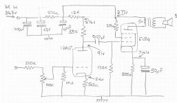
Thought processes and lots and lots of reading and videos led me to decide on a first simple Single ended stereo low power amplifier based on 12AU7 and EL84 combination, being me, I didn't want to just copy an existing design, but build one from the bottom up, using a mixture of calculations and trial and errror.
Therefore I have knocked up a prototype single channel amp so I can fiddle/adjust before making something that really looks good, using own design turret board etc.
Cutting to the chase, if anyone could (constructively) criticize comment on the diagram I have attached I'd be very grateful. The amp sounds quite good really, simple 'scope readings seem to indicate that it has a reasonably flat frequency response although I think it lacks treble and the bass sounds a bit wooly/muffled.
Hopefully as this grows I can use the other half of the 12AU7 as a cathode follower to drive a 3 channel tone stack - but that's for later on !
Many Thanks from a newbie needing guidance, and thanks for allowing me to join the forum.
Steve
As an electronics engineer of some 40 years steeped in transistors and microprocessors I thought I'd have a foray into the world of tube audio which I last dabbled in during the 70's.
Thought processes and lots and lots of reading and videos led me to decide on a first simple Single ended stereo low power amplifier based on 12AU7 and EL84 combination, being me, I didn't want to just copy an existing design, but build one from the bottom up, using a mixture of calculations and trial and errror.
Therefore I have knocked up a prototype single channel amp so I can fiddle/adjust before making something that really looks good, using own design turret board etc.
Cutting to the chase, if anyone could (constructively) criticize comment on the diagram I have attached I'd be very grateful. The amp sounds quite good really, simple 'scope readings seem to indicate that it has a reasonably flat frequency response although I think it lacks treble and the bass sounds a bit wooly/muffled.
Hopefully as this grows I can use the other half of the 12AU7 as a cathode follower to drive a 3 channel tone stack - but that's for later on !
Many Thanks from a newbie needing guidance, and thanks for allowing me to join the forum.
Steve
Attachments
looks ok to me.
the 1000uf might load the power supply a bit on power up ?
i like the 12au7, i have always had noise/oscillation problems with the 12ax7 which has more gain.
if you need more gain bypass 560r cathode resistor with a cap.
the 1000uf might load the power supply a bit on power up ?
i like the 12au7, i have always had noise/oscillation problems with the 12ax7 which has more gain.
if you need more gain bypass 560r cathode resistor with a cap.
Is this supposed to be a guitar amp or a hifi amp? If you want to use this for HiFi, you'll want to triode strap the EL84 or explore adding feedback to deal with the damping issue (and undoubtedly THD as well).
Between 12k and 38 k You can connect 100 uF to ground to separate pre stage and out stage in PS.
2.2 k is like oven in Your amp - use about 30 W resistor/ 0.08x0.08 A x 2.2k is about 13 W/.
2.2 k is like oven in Your amp - use about 30 W resistor/ 0.08x0.08 A x 2.2k is about 13 W/.
Many Thanks from a newbie needing guidance, and thanks for allowing me to join the forum.
Steve
Hey, Steve. There's no point in having two resistors 38K and 12K seperate feeding the 12AU7. They add in series and have no filter between them. So one will do. Second point, you shouldn't branch from the last filter to provide B+ to the outputs and also feed the 12AU7 directly without an additional filter cap ahead of the 12AU7. So at a minimum put a cap between the resistors to decouple the driver from the EL84. And 1000uF is about 1000% overkill for this little amp.
Wow ! Thanks guys, such fast responses !
The 12k and 38k resistors happened because thats what I had at the time of fiddling with values/tagging things in but it looks like they may be worth keeping to follow the suggestion of a decoupling cap between them. I was intending introducing some NFB to the cct as it developed, but to strap the EL84 into Triode mode requires a bit more reading for me 🙂
(I'm learning as i go ahead ).
2020 - thanks, can you explain a bit more please? The 1000uF PSU filter cap was an (partly) attempt to reduce hum, but looking at the construction at the moment - very ad-hoc) of this amp which as now is little more than a test bed, I think there are many more long leads/earth issues to deal with when I settle on a final design to address.
Anyway, many thanks for the advice guys, its much appreciated, keep it coming !
Steve
Hi Audiowize,
Thanks for the advice, I put that in as the output from the CD player I was using as a test source was too high at around 3 v p-p, so I thought a potential divider CCT would help so only a 3rd of the signal could be present at the input at max setting - bad Idea ? Or is this just covering up a bad design ?
Thanks for the advice, I put that in as the output from the CD player I was using as a test source was too high at around 3 v p-p, so I thought a potential divider CCT would help so only a 3rd of the signal could be present at the input at max setting - bad Idea ? Or is this just covering up a bad design ?
but to strap the EL84 into Triode mode requires a bit more reading for me 🙂
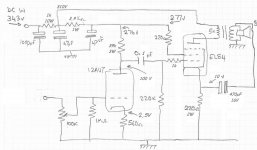
Join screen to plate with a resistor. You've already got a 220R on the screen, so just use that.
jeff
Hi Audiowize,
Thanks for the advice, I put that in as the output from the CD player I was using as a test source was too high at around 3 v p-p, so I thought a potential divider CCT would help so only a 3rd of the signal could be present at the input at max setting - bad Idea ? Or is this just covering up a bad design ?
You have too much gain because you haven't put feedback around the amp. The 220K resistor will work against the Miller capacitance of the 12AU7 and may cause problems.
You will find that triode strapping the EL84 will dramatically improve how the amp sounds and also will change the gain dramatically (in a good way).
2020 - thanks, can you explain a bit more please? The 1000uF PSU filter cap was an (partly) attempt to reduce hum, but looking at the construction at the moment - very ad-hoc) of this amp which as now is little more than a test bed, I think there are many more long leads/earth issues to deal with when I settle on a final design to address.
Anyway, many thanks for the advice guys, its much appreciated, keep it coming !
Steve
By all means work a little GNFB around to the front end. A good starting point for a resistor value in the line would be 10x the driver cathode resistor. Reduce that ratio if you want to add more FB, but 5x would be close to normal limits of FB you could use. As for the 1000uF cap, there are plenty of respected examples of EL84 SE amps using 40uF as the input filter. Then a resistor or small choke and then 40uF for the line to the OPT stage. You have more than that already. If you want to see if more capacitance has any usefull affect just use some jumpers and clip it in. But if you have to go all the way to 1000uf to get hum down then you really have some other problem source or wiring layout. Grounding? Signal line grounds... Or get that driver stage decoupled and see if that helps. My best advice is to look for a Magnavox 196 diagram and learn it for all the good things a great little SE amp has going for it. It has a unique little OPT but it's not critical to build one without the same little tap it has B+ and screen. Have fun with your project.
I think Mona saw that letting Ohms law loose on the voltages indicated in your schematic, especially around the anode resitors and cathode resistor of the first stage, gives faulty results.
How did you measure the voltages in your prototype? Or maybe there are mistakes in your schematic?
How did you measure the voltages in your prototype? Or maybe there are mistakes in your schematic?
Thanks for that advice Jeff and Mona, must admit, wasn't really sure whether to connect the 220 ohm screen resistor to the other side of the output transformer (i.e the plate) or as shown, I'll have a go at these changes this week and report back.
Again, many thanks for your responses, much appreciated !
Again, many thanks for your responses, much appreciated !
Thanks people,
Great advice, voltages could well be out, as I've measured them so many times each time i change components/setup I could well have confused myself.
Anyway, thanks for the advice, first jobs this week are Grid stoppers, Triode strap and GNF all as suggested, I'll let you all know how it goes 1
Thanks all,
Steve
Before you triode strap a perfectly good pentode tube with an OPT that is suited better for it as is than as a triode, do some research on strapping and what it does for power output especially if you do add some GNFB, too. If you go that route you'll end up with less than 1W of usable power.
thanks 20t020, now you mention it, I had read that about the low power, I think that was why I didn't initially explore Triode strapping, I would like and be happy with 5 Watts output which would mean 10 Watts of plate dissipation which I assume would be kind to the 12 Watt EL84. I'll try the GNFB first.
Hi Mona/ guys,
Just experimenting with feedback, Mona, you suggested local feedback and others suggested global feedback, is this just semantics or do you mean applying feedback to the cathode of the output tubes ¿ Sorry in advance if this is a dumb question !
Just experimenting with feedback, Mona, you suggested local feedback and others suggested global feedback, is this just semantics or do you mean applying feedback to the cathode of the output tubes ¿ Sorry in advance if this is a dumb question !
Global feedback would be from the output to the cathode of the input tube, rather than the EL84 shown in Mona's revision in post #10. This would require a resistor to lower the voltage of the applied feedback rather than the capacitor. Sometimes a capacitor is also used in parallel with that resistor, in order to control the phase shift in the feedback to increase stability.
Another local feedback possibility, which is simple to implement, is plate to plate feedback. This only requires a resistor between the anodes of the tubes and is easier to implement than global feedback, because you don't have the phase shift of the transformer.
I have a KT88 amplifier that started out as a simple triode strapped design. I now mostly run it in ultra-linear mode with local, plate-to-plate feedback. The triode strapped mode does have a certain beauty to the sound but the power and frequency response are limited with the transformers I have, so I generally prefer the UL operation so far, over triode. I made the feedback and triode/UL switchable so I can tune the amp to the speakers that are hooked to it. I probably should have prototyped more, as you are, but there can be advantages in a flexible end design.
With half a 12AU7, and than with a cathode capacitor, you will not get more voltage gain than 14 x. Without the cathode capacitor (which introduces local feedback) this will be something like 10 x (estimated, not calculated).
The EL84 at the values in the schematics of TS and Mona, will need about 5.5 V input signal at the control grid for full power.
So with the 12AU7 having a voltage gain of 14 x, the input sensitivity of the amp is 0.4 V for full power. With the 12AU7 having a voltage gain of 10 x, this sensitivity is 0.55 V.
Imho the gain in the first stage of the amplifier is not enough to apply an effective GNFB. Because of that, the local feedback in the first stage in the schematic of TS, and the local feedback in the power stage that Mona added, are about the best you can do under these circumstances.
Just my view. Maybe others do see/hear advantages in just a bit of GNFB.
- Home
- Amplifiers
- Tubes / Valves
- Total Newbie