Hello everyone
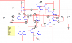
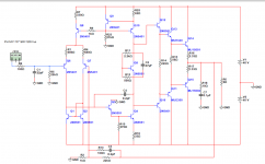
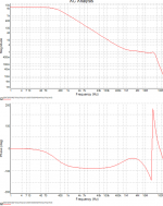
It’s the first time am posting in this forum, in this project I’ve tried to push the amp to the extreme without losing stability, with the help of the books of Mr. Douglas Self and Mr. Bob Cordell I think I’ve achieved an amp with a Phase Margin of 110° and a Slew Rate of about 120V/us, with a very simple 3 stage amp. Till now it’s just simulation, am using Multisim, and the results looks very promising.
Any suggestions is very welcome, hope to find you all in good health and stay safe
Best regards KADER
Attachments

DC connected and response to DC , I hope your previous input equipment contains no leakage of DC ?
DC servo circuits( if applied ) must have an upper working frequency which decides the lower gain limit.
I can see the D.Self influence but not as well up on Mr.Cordell as I would like to be.
DC servo circuits( if applied ) must have an upper working frequency which decides the lower gain limit.
I can see the D.Self influence but not as well up on Mr.Cordell as I would like to be.
Post #3 made me think ---this is a fast amp right ?
I hope you are well up on circuit LAYOUT and that includes the PCB as many fine high speed circuits are not as easy to practically implement as they are on the design board .
To keep within those very small compensation capacitors ability to keep the circuit stable does your software provide a "most stable " layout ?
I have seen many designers having to change layouts several times and the values of original hypothetical compensation capacitor values --hence D.Self,s standard 100pf comp.capacitor which takes care of many problems but as I don't use software maybe I am well out of touch and automatic positional layout circuits are conjured up on a circuit to circuit basis?
Hi Kader,
Not to criticise - please get me right - just sharing some experience.
Simulator is a complicated calculator, so simulation is as good, as good the model is. Although, the embedded models are good enough, simulation does not take in account many parasitic capacitances and inductances, strongly dependant on the layout. So, we can achieve many fantastic characteristics in simulation, that are not possible in the real life.
As already mentioned, small values of compensation capacitors normally look dangerous - in the real life implementation you may be surprised by much lower stability margins.
21193/94 output devices also may surprise you if you didn't practically work with them. Especially in combination with a fast front-end. Those are the "old-school" slow devices, particularly slow in the "closing" phase, resulting in possinbe current shoot-through, killing the output stage. So, as far as you're using those devices in the OPS, you need to implement much more "aggressive" compensation just to keep them safe.
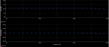
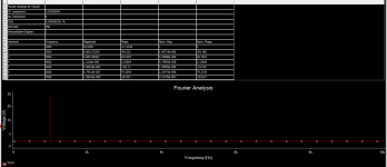
Big difference in distortiion levels at 1KHz and 20KHz tells me the open loop bandwidth of the circuit is relatively low (corrected by a lot os global feedback), which is not good in terms of the way such configuration normally sounds. I prefer wider open loop bandwidth designs.
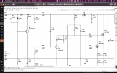
One more thing to mention - drawing quality 🙄 Attached is just an example of what a multisim schematic is expected to look like.
By the way, if you attach a multisim file (zipped) - I can show you some things you probably don't see right now 😉
Cheers,
Valery
Not to criticise - please get me right - just sharing some experience.
Simulator is a complicated calculator, so simulation is as good, as good the model is. Although, the embedded models are good enough, simulation does not take in account many parasitic capacitances and inductances, strongly dependant on the layout. So, we can achieve many fantastic characteristics in simulation, that are not possible in the real life.
As already mentioned, small values of compensation capacitors normally look dangerous - in the real life implementation you may be surprised by much lower stability margins.
21193/94 output devices also may surprise you if you didn't practically work with them. Especially in combination with a fast front-end. Those are the "old-school" slow devices, particularly slow in the "closing" phase, resulting in possinbe current shoot-through, killing the output stage. So, as far as you're using those devices in the OPS, you need to implement much more "aggressive" compensation just to keep them safe.
Big difference in distortiion levels at 1KHz and 20KHz tells me the open loop bandwidth of the circuit is relatively low (corrected by a lot os global feedback), which is not good in terms of the way such configuration normally sounds. I prefer wider open loop bandwidth designs.
One more thing to mention - drawing quality 🙄 Attached is just an example of what a multisim schematic is expected to look like.
By the way, if you attach a multisim file (zipped) - I can show you some things you probably don't see right now 😉
Cheers,
Valery
Attachments
duncan2 thank you for your comments, for the dc part it’s just simulation after you can put whatever please you like a simple capacitor with good value can do the job.
For the small miller capacitor I think that the phase margin is the most important for stability whatever the value of that capacitor is, in this case its 110° I think it’s more than acceptable. And if we take in consideration the stray capacitance the value will add to the miller cap, for example 5pf for stray cap will give you more than 110° of ph M I think.
vzaichenko thank you for your comments, you are absolutely right, and like I said it’s just simulation so it’s gives you an idea about your circuit, but for the phase margin it’s pretty accurate I think and that’s how D.self achieved 94° ph M in his blameless amp, for the slew rate it’s a simple equation to calculate.
Best regards KADER
- Home
- Amplifiers
- Solid State
- extreme ultimate amp