I am using PSUD2 to design a PSU using 5AR4 rectifier.
I think I used too much capacitance, but it can't be helped. During the first second it throws a warning about the IFRM of the rectifier is exceeded.
I'd imagine the rectifier tube isn't warmed up yet at that point and shouldn't be conducting much. Do I need to pay attention to the warning?
Or do I need an inrush current limiter?
Not much to go on. And I never used PSUD2.
Are you aware of, and respecting, the maximum capacity of 60uF right after the 5AR4, when simulating a capacitor input filter? And the minimum values for the total dc-resistance the transformer windings should form (if too low, extra resistors have to be placed in the anode leads of the 5AR4 to reach those minimum resistance values)?
Are you aware of, and respecting, the maximum capacity of 60uF right after the 5AR4, when simulating a capacitor input filter? And the minimum values for the total dc-resistance the transformer windings should form (if too low, extra resistors have to be placed in the anode leads of the 5AR4 to reach those minimum resistance values)?
Pardon me for leaving out the info, the PSU is choke input. The 5AR4 datasheet stated no limiting resistor is required.
What does the graph for rectifier current say? Is it just a single peak, or does it repeat? How much is it pulling over the spec?
Thanks! I didn't know I can do that. 😀
The spike is only at start up lasting less than a second, the peak is at 1.8A, IRFM is 0.75A. After that it remains constant at under 0.3A
The spike is only at start up lasting less than a second, the peak is at 1.8A, IRFM is 0.75A. After that it remains constant at under 0.3A
Schematic?
Maybe too low inductance, too low DCR of inductor, too high first capacitor, too low ESR of capacitor....
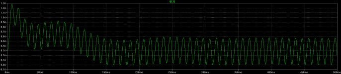
The capacitor is practically short circuit at the beginning, the charging pulses would reach the Amper greatness (until it is charged), the limiting factor is the choke's DCR, the capacitor ESR and the choke inductance (the first charging pulses are practically large spikes).
Sample of bad construction: 5AR4, 1H, 100uF, 300mA load
Maybe too low inductance, too low DCR of inductor, too high first capacitor, too low ESR of capacitor....
The capacitor is practically short circuit at the beginning, the charging pulses would reach the Amper greatness (until it is charged), the limiting factor is the choke's DCR, the capacitor ESR and the choke inductance (the first charging pulses are practically large spikes).
Sample of bad construction: 5AR4, 1H, 100uF, 300mA load
Attachments
Last edited:
You are correct that PSUD doesn't account for slow warm up of a tube rectifier. If you're really worried, you can use a thermistor to slow things down even more.
There is a stepped load function for current taps. Your tubes don't conduct instantaneously so use the stepped function. I generally set the first step for a few mA and then after a second or so step up to the actual current. I stagger the steps from the voltage amp, driver tubes and output tubes so they don't all conduct simultaneously.
- Home
- Amplifiers
- Tubes / Valves
- PSUD2 warning: IFRM exceeded