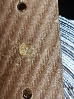
I received my new 8600SVK. Upon opening one of the LL2785s, I noted that a number of the solder pins had been bent. In partucular, a solder pin on the primary had been flattened against the board. Despite carefully trying to straighten the pin, it of course seperated at the board level. 🙁
There looks to be just enough remaining copper lead to pull through to establish a new joint. It also appears the lead is held in place by resin? Presumedly, i would have to apply some heat and carefully push / pull through the remaining copper lead and then build up a layer of solder? I also presume that soldering will melt the insulation?
Has anyone tried this repair with success? (solder temps etc.)
Attachments
I would suggest measuring resistance and/or continuity through the coil and compare it to the known good LL2785 and if it's the same/similar, just get a blob of solder on it and use a leftover leg clipping from an appropriately sized part (try the clipping from one of the diodes in the kit perhaps).
Make sure you apply a bit of flux to it and solder it through the pad and to the OPT at the same time. It should be short enough that it melts both at the same time. Test again for continuity and then move on to the unbroken connections only after you verify it is connected successfully.
Make sure you apply a bit of flux to it and solder it through the pad and to the OPT at the same time. It should be short enough that it melts both at the same time. Test again for continuity and then move on to the unbroken connections only after you verify it is connected successfully.
Alternatively, if you look at it from the side, the other side of the board is going to be a laminated wire. You could try attaching here instead.
Thanks for the tips.
I had a friend at work with better skills than me offer some help. So yeh, managed to push through a pin and solder to the winding on the other side, while keeping the pin held in place with a small blob of solder. Just need to be really careful and not apply too much heat to undo his good work 🙂 And check the resistance like you said.
I'm lucky / glad it was the terminal with better access behind the external metal shield else it would have been a total PITA. Hope this can help someone in a similar situation.
Looking forward to getting this up and running!