My Motu 896 Mk III died during the power outage from the tropical storm. When we got power back, it would no longer power up.
I've replaced the Fairchild Power Switch, recapped the PSU, as well as replaced the optically isolated error amplifier. The diodes all measure good. The line fuse is good. All resistors measure within a couple percent of marked values. Nothing burnt.
I've even tried disconnecting the load and starting the PSU, but only the reservoir cap charges up to 160V.
Basically, I've replaced everything but the transformer. It's starting to seem like that is the failure point, but without schematic, I'm working in the dark and don't know what windings correspond to what pins.
I've asked MOTU if they'd sell me a new PSU module, but they said no.
I may have to give up on repairing this.
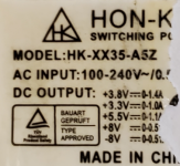
The voltage requirements are a little more than basic.. 3.3, 3.8, 5, -8, +8 volt rails. Almost could use a computer power supply, but don't know if running the 3.8 at 3.3 would pose a problem.
I've replaced the Fairchild Power Switch, recapped the PSU, as well as replaced the optically isolated error amplifier. The diodes all measure good. The line fuse is good. All resistors measure within a couple percent of marked values. Nothing burnt.
I've even tried disconnecting the load and starting the PSU, but only the reservoir cap charges up to 160V.
Basically, I've replaced everything but the transformer. It's starting to seem like that is the failure point, but without schematic, I'm working in the dark and don't know what windings correspond to what pins.
I've asked MOTU if they'd sell me a new PSU module, but they said no.
I may have to give up on repairing this.
The voltage requirements are a little more than basic.. 3.3, 3.8, 5, -8, +8 volt rails. Almost could use a computer power supply, but don't know if running the 3.8 at 3.3 would pose a problem.
You should be looking for the little 0 ohm fusible resistors, make sure they're good.
Basically, I've replaced everything but the transformer
Which one? Switching transformer?
Can you take a few high-res closeup photos and post them here?
Basically, I've replaced everything but the transformer
Which one? Switching transformer?
Can you take a few high-res closeup photos and post them here?
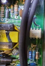
I've measured all resistors. No opens, no burned resistors either.
The semiconductor devices were replaced. The diodes check good (not shorted).
Basically, I'm down to the transformer, which is the larger device (the smaller one is the line filter).
The semiconductor devices were replaced. The diodes check good (not shorted).
Basically, I'm down to the transformer, which is the larger device (the smaller one is the line filter).
Attachments
Those transformers should not have an in-line (in-built) fusible resistor... I think they are most likely okay.
Where is the ON switch wired to?
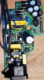
I can not see the switching device (transistor) on that SMPS PCB... is it located underneath?
Can you take a good clean shot of the SMPS connector? I need to see the labels.
I can not see the switching device (transistor) on that SMPS PCB... is it located underneath?
Can you take a good clean shot of the SMPS connector? I need to see the labels.
The power switch is in series with the reservoir rectifier side of the supply. There are no components on the underside of the PCB. It appears that the 'brains' of it are the TO-220 device on the heat sink, which I've replaced earlier.
The output connector pins are as follows in the photo.
The output connector pins are as follows in the photo.
Attachments
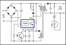
Ok, so the ON switch turns the SMPS on directly. In that case, start from the mains 110V AC input and follow-through:
Bridge rectifier -> storage capacitor (which you checked already - 160V DC)
Flyback oscillator -> switching transistor, which chops that DC at something like 15-30kHz and feeds that to the transformer primary. It seems that the SMPS you have does not use IC to create switching voltages (like TinySwitch IC's..)
You should see the same frequency AC signal at the transformer secondary, at a much lower voltage.
This AC voltage is rectified (usually by) a single diode, for each DC rail (voltage rail).
Since the ON switch controls the mains supply directly to the SMPS, you could use any SMPS that will give you those voltages. NOTE: 3.8V can not be used for 3.3V because some linear regulators are very sensitive to the input voltage rating and will blow if fed by too high a voltage.
You could, however, use + and - 12 V DC supply and then do your own regulation to arrive at all required voltages.
I just gave you a few options above.
It would be good if you could get an oscilloscope to help you fault-find.
Good luck,
Nick
Last edited:
I can confirm that I have 160 VDC at the reservoir capacitor. But I do not have switching happening. It seems that the Fairchild Power Switch (TO-220 like device on heatsink) is the 'brains' of the thing. I replaced that when recapping didn't fix it (I had a cap fail last fall, pulling down the output voltage and making the display go dim and the unit go offline and I replaced that cap and got it going again at the time). When that didn't work, I checked every diode and resistor. When no problems found, I replaced the opto isolator.
I'm pretty much out of ideas.
MOTU will replace it for $99 plus shipping, but I'm reluctant to go that route because I don't want my pristine, like-new unit being replaced with a scratched up unit that smells like an ash tray. Also, my EQ curves and compression settings are stored in this unit and I will lose all of that too.
But I think I have no option. Used ones are going for $450 and up and new are $995-1200.
Make sure the Zener diode is soldered the right way in. Check what datasheet is saying re: pin 4 shutdown voltage.
Make sure the PCB traces are good. You may have cracked a trace, which is sometimes quite hard to see. The flyback transformer should be also checked I suppose.
The circuit is quite simple. Not many things could go wrong...
Make sure the PCB traces are good. You may have cracked a trace, which is sometimes quite hard to see. The flyback transformer should be also checked I suppose.
The circuit is quite simple. Not many things could go wrong...
Attachments
Yes the circuit is quite simple. But there are too many factors and I've spent too much time and $57 on parts and shipping so far. I decided to send it in to MOTU and let them replace it with a refurb unit for $99. I should have done that to begin with.
Have you already sent it?
Do you have startup voltage on pin 3. Data sheet says it may need up to 40uA at 13V to take off. If the designer wanted to cut it thin, the resistance providing it could be up to 3m7. It wouldn't take much of a leakage path (repair soldering flux, with humidity effects) to thwart that.
The external circuit may very well be simple, but the FSCM0765 is packed with protection mechanisms. $99 for a refurb sounds like a bargain to me, too.
We've all done it. Don't kick yourself.
Cheers
It went out USPS yesterday.
I am pretty sure it took a power spike when the electricity went out last Tuesday from the storm. Customers are still out of power as of today, ore than a week. But the power went off and on several times before it went off, causing my UPS to kick and out several times. When we got back on generator power, that's when I noticed no life in the MOTU.
I am hoping I get an identical unit and not one that is scratched up and smelling like cigarettes. The unit I had was particularly quiet, with no audible hiss. Hopefully the replacement will be identical. I just have to go through configuring EQ and compressors and all that stuff again, because I recall that is all stored in the MOTU not on the PC.
- Home
- Source & Line
- Digital Source
- MOTU 896 Mk III Power Supply Problem