I am using a 1578 Russian tube to drive my 300B. I was given these parameters for proper sound. Unfortunately I am not advanced enough in my theory to completely understand the meaning. Any help would be appreciated on how to measure and achieve these numbers. Thank you.
ua 250b
uc 8
Ra 10k-12k
ua 250b
uc 8
Ra 10k-12k
Ra is the plate resistance, imho it's more important than transconductance as a measurement with these fancy solid state filament rectifiers.
A low plate resistance will couple to the filament and skip the cathode in most cases and the tube won't impact the sound much. Indirectly measuring filament current draw is a futile attempt at good sound.
A restored tube, cryogenisis or just one left to sit for a long while can measure well for plate resistance but it can fall incredibly fast. The benefit is the tube will retain the spacial distribution of remainder ions in the tube and it will rejoin to the cathode after the pull due to the filament being off and the cathode being a better ground for incoming solar charging than whatever leaks through the off power switch to the anode
The tube still has to sit for a long while after the pull (intensity of Ra) or from a table (duration of Ra) due to the amount of oxide that has settled on and in the porosity of the glass enclosure which will directly block the effect of the newly placed tube to transconduct to cathode in a equatable corrliatable timeframe to the second (or 1000th(power on/off)) death of the plate resistance.
The problem is residual ion distribution only really matures and builds upon itself with the filament on...
Last edited:
The true proof test will always lie in the inductive vs reactive load. Thus transformers will always rule as unique satisfying sound. They do produce better reactive sound over the long haul being left on with as minimal as necessary tube/part changes.
The 1578 is equivalent to a 6SN7GT and as long as you are not seriously exceeding any of its ratings you are good to go. It's reputedly of better than average build quality, I no longer use 6SN7 in my designs and haven't tried the 1578 (they were sort of difficult to get in that time frame.)
ua 250b
uc 8
Ra 10k-12k
ua is anode voltage, uc is likely cathode voltage, Ra is plate impedance.
Is Brightcity meatware or a spam bot?
Is Brightcity meatware or a spam bot?.....I vote spam bot.
Audio guru in training, filtered through Google translate.
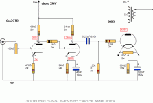
With Ohm's law, I calculate B++ to be around 380 V.
Looking at the curves of the 6SN7GT(B), I think that to get the 4.1 mA flowing with the voltages indicated around the second triode, the voltage difference between the cathode and the grid of the second triode will have to be about 7 V instead of the 8 V indicated in the schematic.
But these are minor details. The second triode will settle automatically anyway.
Last edited:
"The best option for this 250v lamp." Here is a schematic.
I got restarted in the tube amp world in the 1990's, mostly building guitar amps and push pull HiFi amps. I decided to build a SE HiFi amp around 2000 to see what all the fuss was about. The most popular 300B schematic was this one. There was a power supply schematic that featured a 5U4 and a CLC filter. Yes, the B+ was around 375 to 400 volts.
I built one and played with it for a while, but eventually grew tired of it and started down the "design my own" rabbit hole which eventually led to the TSE design.
It is still not a bad place to start if you want to use the tubes you have.
- Home
- Amplifiers
- Tubes / Valves
- 1578 tube
