The amp will operate without the two 1N5266B zeners. I typically remove them but if that's done, you must insert a wire jumper in any through hole that connects the top and bottom of the board. If that's confusing, you can leave them in the circuit.
I'd suggest removing any component that is in an area that overheated (even slightly) and desoldering its leads, scraping them to bare copper and re-tinning them. Do the same for any pads that overheated.
The best way I find to get the bare copper on the board is a fine stainless wire brush and then a fiberglass scratch pen but any way that you can get to clean copper is OK.
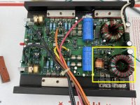
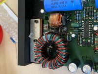
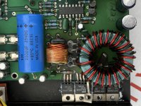
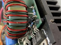
This especially applies to the two 22 ohm resistors under the second 'transformer'.
Any solder connections that have pads top and bottom should be soldered top and bottom. Don't rely on any overheated vias.
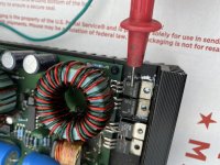
I'm not sure what the proper term for the second transformer is (coil? flyback transformer?...) but it's used to give a bit more boost to the voltage, I think (it's been a long time since I've worked on these). If you want to confirm, look at the amplitude of the output from the first transformer then the output at the input to the rectifiers.
I'd suggest removing any component that is in an area that overheated (even slightly) and desoldering its leads, scraping them to bare copper and re-tinning them. Do the same for any pads that overheated.
The best way I find to get the bare copper on the board is a fine stainless wire brush and then a fiberglass scratch pen but any way that you can get to clean copper is OK.
This especially applies to the two 22 ohm resistors under the second 'transformer'.
Any solder connections that have pads top and bottom should be soldered top and bottom. Don't rely on any overheated vias.
I'm not sure what the proper term for the second transformer is (coil? flyback transformer?...) but it's used to give a bit more boost to the voltage, I think (it's been a long time since I've worked on these). If you want to confirm, look at the amplitude of the output from the first transformer then the output at the input to the rectifiers.
I put in those rfp15n06 to test that part of the power supply once I removed the defective fets. It just overheated one of them and it shorted fast within seconds. I’m not sure why but the amp does emit sound but it’s not as strong.
The 15N06 probably isn't going to work. You need a higher voltage FET. If one is overheating, it's likely not getting driven correctly. Did you do what was previously suggested?
You were right sir! The gate pad was not being conductive on the FET that kept going out. Was not being driven due to a non conductive gate vias underneath the board. I had to solder a jumper wire to the resistor. Bam! No more fets blowing out.
Ok I’ve got another issue with this amp. The buz10 side is getting hot when the amplifier is playing at a higher volume the sound cuts out and the buz10 side gets hot. I installed new IRF540 in the other side and it’s working now the whole amp is just cutting in and out when turned up.
Does either channel, playing alone, play normally at high volume?
Are the primary filter capacitors within tolerance?
Are the primary filter capacitors within tolerance?
- Home
- General Interest
- Car Audio
- Rockford fosgate Punch 150 1st gen need help with it