Firstly thank you to the folks on here who have introduced me to the dim bulb tester. If only I'd found this earlier I would have saved my self from quite a few pyrotechnic episodes!
So to the point of this post, my faulty 3240. Being a newbie to electronics I'm on a steep learning curve. I purchased this amp with a silent left channel, however, as I intend to keep this one for my own use in my study for a while, I decided to go to town on it, expecting to locate the faulty component(s) along the way.
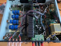
So, I replaced all the electrolytic caps, testing as I went. All still measured to spec, so this is purely for quality upgrade, not fault fix. The main power caps I up'd to 10,000uF from DNM.
I also removed all of the transistors and tested them using the voltage drop on my diode tester. Again, all measured okay. The power transistors were replaced from a reliable source, not eBay(!) with like for like.
I fitted an external IEC power socket to get rid of the original NAD mains cable in favour of one from Lapp. Finally, I added new speaker binding posts in solid copper with 14 gauge wire running directly from the underside of the board from the speaker connection points for speakers A. This bypasses the horrid originals and the truly nasty four way plug on the speaker post board.
I also hard wired the preamp out to the power amp in, eliminating the need for external links going through RCA sockets on the rear panel.
So to the issue. I connected the amp to the mains using my freshly built dim bulb circuit and switched it on. The lamp came on and stayed on. This seems to me to be indicating a short.
I carried out a quick visual inspection and found a horrific error in my wiring. I had reversed live and neutral on the socket. A complete brain fade on building it. I put it down to being made redundant by C-19!
Anyway, I rewired the socket and went for it a second time, ensuring the DBT was safely in place. Unfortunately it failed to bring the amp back to life and the DBT shines brightly.
I now need to diagnose the issue and I would welcome any suggestions.
So to the point of this post, my faulty 3240. Being a newbie to electronics I'm on a steep learning curve. I purchased this amp with a silent left channel, however, as I intend to keep this one for my own use in my study for a while, I decided to go to town on it, expecting to locate the faulty component(s) along the way.
So, I replaced all the electrolytic caps, testing as I went. All still measured to spec, so this is purely for quality upgrade, not fault fix. The main power caps I up'd to 10,000uF from DNM.
I also removed all of the transistors and tested them using the voltage drop on my diode tester. Again, all measured okay. The power transistors were replaced from a reliable source, not eBay(!) with like for like.
I fitted an external IEC power socket to get rid of the original NAD mains cable in favour of one from Lapp. Finally, I added new speaker binding posts in solid copper with 14 gauge wire running directly from the underside of the board from the speaker connection points for speakers A. This bypasses the horrid originals and the truly nasty four way plug on the speaker post board.
I also hard wired the preamp out to the power amp in, eliminating the need for external links going through RCA sockets on the rear panel.
So to the issue. I connected the amp to the mains using my freshly built dim bulb circuit and switched it on. The lamp came on and stayed on. This seems to me to be indicating a short.
I carried out a quick visual inspection and found a horrific error in my wiring. I had reversed live and neutral on the socket. A complete brain fade on building it. I put it down to being made redundant by C-19!
Anyway, I rewired the socket and went for it a second time, ensuring the DBT was safely in place. Unfortunately it failed to bring the amp back to life and the DBT shines brightly.
I now need to diagnose the issue and I would welcome any suggestions.
Last edited:
Looking at the schematic Live/Neutral reversal won't make a difference as it just feeds into the transformer.
Complete removal of transistors is a very thorough way to test... worth making sure you put everything back in the right place, and check all soldering.
Complete removal of transistors is a very thorough way to test... worth making sure you put everything back in the right place, and check all soldering.
Okay, will do. And thanks for the reassurance about the reverse live/neutral error.
I did the same removal/test procedure recently on a NAD C370 and found a dud transistor in the process. All fixed now and sounding great.
I did the same removal/test procedure recently on a NAD C370 and found a dud transistor in the process. All fixed now and sounding great.
Are they isolated from the chassis ? If not the outputs are short.I added new speaker binding posts
I believe in Britain the main sockets are "polarised", They fit only one way, but it doesn't matter if You switch Neutral & Live. Schuko European sockets fit both ways and my amp is happy both ways.I had reversed live and neutral on the socke
Rule out the PSU first. Disconnect the amp PCB from the PSU (leave only trafo rectifier & main caps). Does the lamp also shine bright ?
Was it serviced before ?
Check isolation between output drivers & chassis.
Could be a missing / punctured mica or isolation washer on the screws holding the output transistors.
Check for bad solder pads. My old Pioneer amp had a broken resistor which forced the output to go high (VU was pegging) after a few seconds.
Check if there are those unobtanium SV3H or SV4H triple or quadruple diodes.
If they break or fail, output usually goes high.
Hi Maaco
Thanks for the advice. The speaker posts are good, I've checked for continuity between +ve and earth and there is none.
As regards servicing, there was no sticker inside to indicate such and it looked original, that is, very dirty.
I'll run through your other suggested tests as well. I'll start by removing the screws from the output transistors and pulling them off the heat sink. I've already backed off the adjuster pots ready for setting up, which includes removing a couple of solder shorts across two 1R resistors.
If you removed the circuit board, make sure that it is clipped back into the chassis properly. I had one recently that had been worked on previously and the AC section of the board was in contact with the double insulated (i.e. not earthed) chassis waiting to bite..
You mentioned that one channel was silent already - this could mean an already short output or diodes as MAAC0 says.
Might be worth disconnecting the preamp from the amp section again to isolate the short.
You mentioned that one channel was silent already - this could mean an already short output or diodes as MAAC0 says.
Might be worth disconnecting the preamp from the amp section again to isolate the short.
That's a great shout, thanks. I'll go and check that now. In the meantime I was ordering caps for another project so tagged on a set of three bridge rectifiers whilst I was at it.
I've hard wired the preamp to the power amp but that's easy to decouple. Wanted to remove those links from the chain as I have no intention of using the two parts separately.
I've hard wired the preamp to the power amp but that's easy to decouple. Wanted to remove those links from the chain as I have no intention of using the two parts separately.
Had some time so went back to the amp. There are three pairs of fuses in the system, all post smoothing caps, two, 4A & 5Am going to the power amp side and 1 pair of 1A going to the pre-amp. Having removed my soldered links between pre-amp and power amp, as well as the extra speaker links, just in case, I tested again.
With the preamp fuses in only, bulb went out, so all looks good there. With either pair of power amp fuses in the DBT lit up. So, problem halved.
I then plugged the links in between the pre and power amps in again and tested again with only the preamp fuses in place. No lamp, leading me to the conclusion that the power amp signal path is not going to earth. So, it's in the power supply side of the power amp.
Next I set about tracing the power supply path on the schematic and removed the diodes in pairs along the lines, testing at each point. Short circuit every time.
Finally, I removed all 4 of the power transistors and associated 6 smaller transistors on the heat sink. Now the lamp flares and dims, but never quite goes out. I also had a very slight burning smell first time I switched on.
Switched off immediately and tried to detect the source of the smell or any residual heat in the components. None found. I then switched it back on to see if I could spot the issue. Again none found but now no smell, lamp still showing dimly. All transistors seem to be measuring voltage drops across B-C and B-E as expected and they are new.
Apologies for the ramble, but I am now wondering just what to conclude from all my tests. Have I got a duff transistor, even though it measures correctly? Or more likely, have I removed so much from the board that I have isolated the short? Also, I tried the DBT on a known good amp and the bulb went out completely. What does a dim bulb indicate? Is there a very slight short?
This is not a commercial exercise, it's about me learning a bit more about amps and finishing up with a nice little vintage amp for my study. Any pointers from here most welcome.
Last edited:
The proper way to have done this would have been to compare the base-emitter voltages of all the transistors in the faulty channel with those having the same function in the working channel. You could check your soldering to see if there are any inadvertent short circuits between traces.
I make enough bad solder joints, I do voltage tests on class AB amplifiers before I remove & replace parts. It certainly isn't getting better in my seventh decade. Vce is usually from 1/3 to 2/3 of supply voltage, diode voltage should be >1 v backwards, capacitor voltage should be non-zero across it, resistor voltage should be less than that which would burn it out. Resistor wattage = (v^2)/r, you can guess the wattage by size.
Thanks for the advice folks. I have now checked the soldering across the entire board several times and can find no obvious issues.
My working assumption is that I still have a short, which is now being partially masked by the removal of the power transistors. I think the next components to check will be the remaining caps. I've already changed all the electrolytics and the poly caps are spot on.
I have an upgrade to all of the 1W carbon film resistors on the way too. These will be Takman metal films. When this thing finally comes to life it should sound amazing!
Fitted the Takmans and found one of the 1/2W resistors in the soft clipping circuit was OL. I think this happened when the transistors came out, but I think I may have located the area where the fault is.
I have replaced the 8K2 1/2W resistor R413,414 & R423,R414. At the same time I will replace Zeners D405 & 6 and also regular diodes 401-4. After this I'll reassemble and retest.
Cheers
I have replaced the 8K2 1/2W resistor R413,414 & R423,R414. At the same time I will replace Zeners D405 & 6 and also regular diodes 401-4. After this I'll reassemble and retest.
Cheers
By way of an epilogue, I thought those who had contributed might like to know how I finally "fixed" the amp.
Now in my defence I said up front that I am a newbie at electronics and whilst many on the forum are deep in the wisdom of the electron, I'm still on the hard yards. Whilst tackling a Musical Fidelity E1 I came upon a set of testing procedures. Obviously, these are model specific, however, there was one part of the procedure that seemed to make sense for all amps.
Specifically, set the bias pot's to the lowest setting, being fully anti-clockwise, before powering on and bringing up the voltage gradually. So, not a bad idea, however, if you do the same on the 3240, it actually sets the voltage to maximum, hence, a short circuit is indicated.
Now all my work on the amp did find the broken resistor, which caused the left channel issue, however, there was clearly no fault to find. Just my rookie error. I set the pots to full clockwise then wound them open by 1/3 as a start point. I then followed the procedure in the service manual and it worked like a charm.
The amp is now installed in the office, happily doing its duty with the rest of the system and it sounds great. Can't wait for the caps to run in.
Thanks again to all those who helped and I now have several more tools in my kitbag for the next one. Speaking of, that's a Marantz PM40SE which I recently blew up!
Attachments
- Home
- Amplifiers
- Solid State
- NAD 3240 short