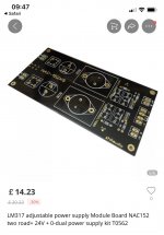
I am new to this site so apologise up front for my lack of understanding. I have see a clone power supply board as a copy for. A naim nac152 preamplifier power supply advertised on AliExpress and ebayuk it is advertised as a nac152 lm317 dual +24v adjustable power supply kit. It shows a four terminal connection for -v 0 +v can anyone tell me what this should connect to ? I assumed it might be a potentiometer to adjust the voltage output but as I’m a newbie to all this I really don’t know? Any answers will be appreciated ! Thank you ! Lm317 adjustable power supply Module Board NAC152 two road+ 24V + 0-dual power supply kit T0562 I’ve tried to attach a photo as an attachment to help . Thank you all.
Attachments
To me it looks like a board containing two independent 24 volt supplies. In other words + 24 and +24 with no interconnection between them.
The presets on the board set the output voltage.
The terminals I imagine are just parallel sets of terminations meaning two for each connection. So you have +24 and +24 and 0 and 0 for one independent supply and the same again for the other.
The board needs a dual secondary (not a split secondary) transformer in order to maintain the isolation between the supplies.
That's how it looks to me.
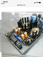
Thank Mooly I’m still unsure so have added another photo . It shows what I assume are the ac inputs connections from a toroidal transformer and then the output stages at the other end of the board but with dc out connections +v ground , -v (0 linked) +v, ground +v . I guess the easy option would be to buy the board build the module and then test with a multimeter. Thanks again
Attachments
To be certain how all those output pads are configured needs you to see the underside of the board but everything points to it being two independent +24 volt supplies with no interdependency or interaction.
How you connect them at the output is up to you.
Perhaps the centre group is an option to connect in a way to get a split supply or perhaps they carry the unregulated supply in case the user wants to use those for something.
How you connect them at the output is up to you.
Perhaps the centre group is an option to connect in a way to get a split supply or perhaps they carry the unregulated supply in case the user wants to use those for something.
I think I’ve cracked it the 0 v is linked and uses the -v and +v four screw terminal to provide a single power output by putting the two supplies in series. If I want two dedicated output power supplies then I use the two outer two terminal g and +v outputs. Thanks again for you help. I’ll make sure I get the correct transformer supply as you mentioned kind regards Colin.
🙂 we thought alike on that one.
Make sure you don't get a transformer with to high a voltage rating.
24 volts DC output needs a few volts headroom for the regulator, so lets say 30 volts DC at the input to regulator. That would need around 22 volts AC input from the transformer.
Remember that the transformer voltage will be a little higher than stated at light loads and by an amount related to the 'regulation' figure in the data sheet.
That’s great ! I didn’t know that so thank you for all you help. I’ll do as you suggest ����
- Home
- Design & Build
- Parts
- Nac152 power supply clone board lm317