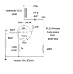
Having read good things about it, I bought some PL33 which is the EL33 equivalent with 19v heaters at 300mA. EL33 is derived from the EL3N which has generated some good reports from users.
So I was wondering about triode operating points, and came up with the attached. I'd welcome some feedback from anyone familiar with EL33 or similar line stages. It's probably not too far away from a 6V6 for example. I'd be using it to drive a 300b.
So I was wondering about triode operating points, and came up with the attached. I'd welcome some feedback from anyone familiar with EL33 or similar line stages. It's probably not too far away from a 6V6 for example. I'd be using it to drive a 300b.
Attachments
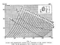
Try for example 210V, 25mA, -6V operating point.
BTW this tube not a champion of low out resistance tubes race.
Without stepdown interstage or CF/SF IMHO not optimal driver for 300B.
BTW this tube not a champion of low out resistance tubes race.
Without stepdown interstage or CF/SF IMHO not optimal driver for 300B.
Last edited:
The datasheet load(line) usually twice as Ra, so 7k load means ca. 3k5 Ra.
p.s. I found the datasheet: trioded Ra: 3k.
p.s. I found the datasheet: trioded Ra: 3k.
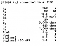
The ra can vary depending on the tube/valve maker , I usually go by Mullard who say its =4.5k,whereas Mazda has 4k for an EL84.
Ra for an EL33 in triode mode is 3k Ra in some books is load resistance but in other equivalent books its RL there seems to be a change in the wording in later years this might cause confusion.
Ra for an EL33 in triode mode is 3k Ra in some books is load resistance but in other equivalent books its RL there seems to be a change in the wording in later years this might cause confusion.
andyjevans
Calculate rp.
Look at the slope of a grid curve (post # 1, Triode curves).
Example, on the -6V grid line;
12.5 mA @ 180V
37.5 mA @ 240V
240V - 180V = 60V change
37.5 mA - 12.5 mA = 25 mA change (0.025 A)
rp = 60V / 0.025A = 2400 Ohms.
Note: Below 12.5 mA, the grid line slope is lower (upward from left to right), which gives a higher rp.
Now you can do this for your particular quiescent operating point.
Last edited:
andyjevans,
I forgot to mention that the cathode resistor, 167 Ohms without a bypass capacitor does raise rp to a higher resistance.
At mid frequencies, the choke is a high enough impedance, the gain remains almost the same.
But at low frequencies, the choke inductive reactance goes down, so the gain goes down because more signal is developed across the 167 Ohm cathode resistor.
And at high frequencies, the choke distributed capacitance's capacitive reactance goes down, so the gain goes down because more signal is developed across the 167 Ohm cathode resistor.
- Home
- Amplifiers
- Tubes / Valves
- EL33 line stage or driver tube