Hi, got this amp in with blown output FETs.
Ordered in some parts, installed both new 4420 and optocouplers. All signals were verified with output FETs out of the main pcb. On one 2211 (u9) pin 7, the signal was a bit fuzzy/ring down but not to distort the drive signal. The opposite signal was perfect. I went ahead and installed the output FETs, amp powered up nicely.
Whilst powered and checking the gain the pot, I noticed the amp would get extremely noisy beyond half way on the gain pot (~ 32v rms at the output). I backed it off a bit until where I just about started losing the sine wave on the output. Whilst attempting to verify the drive signals I accidentally shorted one of the output FETs and I blew a couple.
I then returned to square one, removed and replaced components as I went along returning the drive signal. I am out of output FETs, 2240 and 2211, which I have on order.
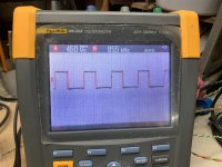
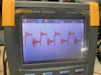
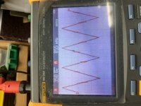
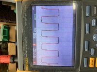
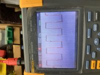
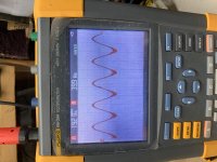
However I noticed a clean square wave on pin 2 of U9, but it gets fuzzy at its output pin7. Same as earlier before I soldered in the Output FETs. I checked the resistors and capacitors around the 4420 and U9 but all check ok. I’ve attached a couple pics of the waveforms. The first pic is the signal entering the 2211 at pin 2. The other pics are pin 7, pin 1 on the 2211 and the gate pad of the FETs. For now I’ve got to wait on parts, but seeing I had a fuzzy drive signal at first and still has, is there something I’m overlooking?
Ordered in some parts, installed both new 4420 and optocouplers. All signals were verified with output FETs out of the main pcb. On one 2211 (u9) pin 7, the signal was a bit fuzzy/ring down but not to distort the drive signal. The opposite signal was perfect. I went ahead and installed the output FETs, amp powered up nicely.
Whilst powered and checking the gain the pot, I noticed the amp would get extremely noisy beyond half way on the gain pot (~ 32v rms at the output). I backed it off a bit until where I just about started losing the sine wave on the output. Whilst attempting to verify the drive signals I accidentally shorted one of the output FETs and I blew a couple.
I then returned to square one, removed and replaced components as I went along returning the drive signal. I am out of output FETs, 2240 and 2211, which I have on order.
However I noticed a clean square wave on pin 2 of U9, but it gets fuzzy at its output pin7. Same as earlier before I soldered in the Output FETs. I checked the resistors and capacitors around the 4420 and U9 but all check ok. I’ve attached a couple pics of the waveforms. The first pic is the signal entering the 2211 at pin 2. The other pics are pin 7, pin 1 on the 2211 and the gate pad of the FETs. For now I’ve got to wait on parts, but seeing I had a fuzzy drive signal at first and still has, is there something I’m overlooking?
Attachments
-
 61BFD41D-34F7-40B2-AE6F-B188D569E6E4.jpg994.6 KB · Views: 97
 -
 1AF18E77-3E98-4E82-A7D4-17592E0635CB.jpg998.9 KB · Views: 99
 -
 4AE6CCD9-52A5-41C8-AAD5-92F47A696ADE.jpg994.1 KB · Views: 90
 -
 71E9F56B-EB57-49BE-800F-1550C43E4F34.jpg991.9 KB · Views: 91
 -
 C79A7103-CDA4-46BB-A281-649DFA0B4140.jpg993.9 KB · Views: 92
I don’t believe the gain pot is causing the problem, but I can’t confirm until I get replacements. I found it strange though after replacing with new components one side had a perfect drive signal and the other was fuzzy, on two occasions. I’m not sure if you guys have seen this before.
You have to reduce the variables. Using the gain to adjust the level instead of the signal source complicates things.
Set the gain where the signal is clean and see if increasing the level with the signal source to see if the amp reacts the same way.
If the signal source shield isn't grounded, ground it or use a signal source with a grounded shield.
Set the gain where the signal is clean and see if increasing the level with the signal source to see if the amp reacts the same way.
If the signal source shield isn't grounded, ground it or use a signal source with a grounded shield.
Yes you’re correct. Initially while ruling out the gain pot I adjusted the input signal, it wasn’t the gain pot causing it. I have a small 12v signal generator I use to send a sine wave into the UUT. After adjusting the SG to where I was just about losing the sine wave on the output, I started probing the gates of the output FETs when the probe slipped. I rebuilt the drive signal up to the optocoupler for now.
Did you discharge the filter caps?
There is virtually no way to damage the FETs with no rail voltage?
There is virtually no way to damage the FETs with no rail voltage?
The filter caps were discharged with a 4.7k resistor, can’t remember the wattage offhand. The HV wires were unsoldered prior to rebuilding the drive circuitry the first time when I noticed the fuzzy drive signal on one of the optocouplers. Everything check ok except for this fuzzy drive signal.
I then soldered in the Mesa with the FETs, HV wires and applied a signal and power. This is where I noticed I was losing the output waveform.
Whilst probing around is where the probe slipped and I fried the FETs.
I unsoldered the HV wires again whilst rebuilding the drive signal a second time, yet again I noticed the fuzzy drive signal on the same optocoupler ( replaced with a second new).
Is the triangle waveform on pin 7 of U11 swinging to about ±5v.
What's the DC voltage on pin 2 of U5 and U8 after the mute delay has ended?
What's the DC voltage on pin 2 of U5 and U8 after the mute delay has ended?
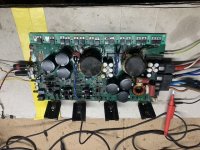
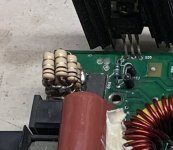
Post a photo of the drive on the output FETs (one 3415 and one 6215) with the scope directly on the gate and source pads.
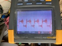
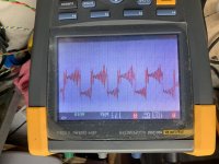
I’ve installed four output FETs, one each. I’ve connected my 8ohm dummy load and I’m sending a 40hz signal to the inputs. The second waveform is across the 8 ohm loaf.
Attachments
I don't see a problem. There is a bit of carrier getting through the filter circuit but that's not unusual. You can check the output filter caps to make sure that they're within tolerance and don't have any broken leads. If they're OK, the amp is likely OK.
- Home
- General Interest
- Car Audio
- Rockford fosgate bd1500.1