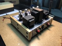
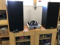
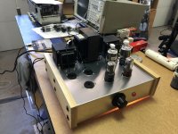
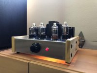
The 6DQ6B is a tube that pops up time to time on this forum (usually in threads praising the virtues of TV tubes) but I've yet to come across many examples of projects built around this tube. On that note, I would like to present my latest completed project: a 20WPC stereo amp that uses the 6DQ6 in push-pull triode mode.
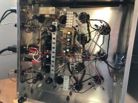
The goal of this project was to make a reasonably powerful stereo amplifier that made use of a power trafo and two HH Scott OPTs that I'd been trying unfruitfully to find an application for. The OPTs are 8K a-a with 4, 8, and 16 ohm taps; originally paired with EL84 tubes. I also had a bunch of 6DQ6Bs lying around from a previous failed project. In my experimentation, I found that using 8 ohms across the 16 ohm tap provided a 4K load that a pair of triode-mode 6DQ6Bs seemed to like. Despite warnings about screen grid max voltage ratings, these tubes seem to play nice with only 300V B+. At a quiescent OP of 50mA per tube, the bias is upwards of -50V and the plate dissipation is 15 Watts.
I don't have the means to test the distortion or frequency response, but I can say that this amp sounds quite good to my ears. Then again, nothing sounds better than an amp you built yourself 😀 For those interested I've attached the LTSpice sims and some more explicit schematics via PDF. Hopefully one day it might be of use to someone who also has interest in this tube.
Attachments
-
V2 - 6DQ6 Triode PP AMP.asc7.2 KB · Views: 392
-
6DQ6 PPT Audio Schematic.pdf61.7 KB · Views: 543
-
6DQ6 PPT PSU Schematic.pdf59 KB · Views: 403
-
 IMG_1704.jpg873.6 KB · Views: 764
 -
 IMG_1693.jpg949.9 KB · Views: 544
 -
 IMG_1703.jpg771.8 KB · Views: 531
 -
 IMG_1709.jpg978.9 KB · Views: 606
 -
 IMG_1700.jpg898.7 KB · Views: 621
 -
 IMG_1706.jpg733.9 KB · Views: 349

Make those screen grid resistors larger and the B+ voltage can climb. The Russian 6Π15Π (6p15p) has a 150 V. screen limit, but otherwise electrically resembles the EL84. Large screen resistors, say 1 Kohm, in the triode strapping role make the 6Π15Π quite nice. The same "trick" should work with the 6DQ6.
Heat, not mere volts is the "enemy". Adequate current limiting saves the day.
Heat, not mere volts is the "enemy". Adequate current limiting saves the day.
Eli, good point. Thermal runaway is something I have experienced before with the 6DQ6 (because of my poor design). If I were to raise the B+ I would have to do some more serious current limiting. The flip side is the negative bias requirements get a little ridiculous if you want to stick to triode mode with these sweep tubes.
Jerdy,
Good design, good looking, and nice implementation (very well executed).
The 6DQ6B g1 does have over 220k return to ground.
Could be a problem if one tube heats and goes slightly gassy.
Thermal runaway has caught me more than once.
The current sourced cathode coupled phase investor 6SN7 stage can drive a load less than 220k.
That may require a little higher capacitance in the coupling caps (I did not check the -3dB point).
Triode Mode is easiest on the screen of a Beam Power tube, versus a given operating voltage. As the plate voltage goes down to 50V, the screen follows it to 50V (instead of in Beam Power mode where the screen is still at 175V, or in Ultra Linear where the screen is still around perhaps 150V). Check the screen current on a set of tube curves, and you will see that.
The issue of screen dissipation in triode mode is at the quiescent point.
The issue of screen current in Beam Power and Ultra Linear Modes is when the plate swings low to 50V.
A Guitar amp has this issue, when heavily overdriven to the point of a square wave (push and pull screens are at maximum current 50% of the time).
Hi Fi . . . not an issue, nobody but the deaf listen to constant 100% square wave clipping.
Just increasing the g2 resistor may take care of screen dissipation, and help with thermal run-away, but may also change the power and distortion too.
Again check the tube curves.
proper g1 resistance may prove more helpful to reliability.
The g1 bias is well designed, if either pot wiper opens, g1 will go more negative (instead of going less negative which is hard on the tube).
Your good work ends in great listening sessions.
Last edited:
6DQ6B is equivalent to 6JN6, 6GE5, 6GV5, and 6FW5 except for basing. You'll find a few of those have been used for amplifiers also. Like Pete Millett's Engineer's Amp. 6JN6, 6GE5 and 6FW5 don't have the plate cap.
6DQ6B is equivalent to 6JN6, 6GE5, 6GV5, and 6FW5 except for basing. You'll find a few of those have been used for amplifiers also. Like Pete Millett's Engineer's Amp. 6JN6, 6GE5 and 6FW5 don't have the plate cap.
Pete Millett's Engineer's amp was actually one of the references I used when planning out my project, particularly for the power supply.
Jerdy,
Good design, good looking, and nice implementation (very well executed).
The 6DQ6B g1 does have over 220k return to ground.
Could be a problem if one tube heats and goes slightly gassy.
Thermal runaway has caught me more than once.
The current sourced cathode coupled phase investor 6SN7 stage can drive a load less than 220k.
That may require a little higher capacitance in the coupling caps (I did not check the -3dB point).
Triode Mode is easiest on the screen of a Beam Power tube, versus a given operating voltage. As the plate voltage goes down to 50V, the screen follows it to 50V (instead of in Beam Power mode where the screen is still at 175V, or in Ultra Linear where the screen is still around perhaps 150V). Check the screen current on a set of tube curves, and you will see that.
The issue of screen dissipation in triode mode is at the quiescent point.
The issue of screen current in Beam Power and Ultra Linear Modes is when the plate swings low to 50V.
A Guitar amp has this issue, when heavily overdriven to the point of a square wave (push and pull screens are at maximum current 50% of the time).
Hi Fi . . . not an issue, nobody but the deaf listen to constant 100% square wave clipping.
Just increasing the g2 resistor may take care of screen dissipation, and help with thermal run-away, but may also change the power and distortion too.
Again check the tube curves.
proper g1 resistance may prove more helpful to reliability.
The g1 bias is well designed, if either pot wiper opens, g1 will go more negative (instead of going less negative which is hard on the tube).
Your good work ends in great listening sessions.
Thanks for the detailed feedback. g1 resistance wasn't chosen carefully for the application; I just knew that combo would give me the target -3dB. I will keep this change in mind for when I inevitably start tinkering with the circuit again. Also you make a good point about triode mode being easiest on the tube grids; I hadn't thought about it in that way before. I appreciate that you took the time to look over the design 🙂
- Home
- Amplifiers
- Tubes / Valves
- 6DQ6B/6GW6 Push-Pull Triode Amp