My mom dropped off her SR508 for me to repair. Found shorted output transistors on the back left. Wonderful person in this thread Replacements for SA1941 and SC5198 helped me out with some replacement output transistors. Got those replaced. Also replaced open emitter resistor on those output transistors.
Then found fuses to amp board were blown. Replaced those.
Unit now shuts down after power up. Found the emitter resistor on one of the drivers was blown (open, should be 100R). Replaced that (temporary currently since these amps SUCK to get the main board out of.
Unit is still shutting down for some overload. Thermal camera shows the output transistors and emitter resistor for them getting hot. But they seem fine (no shorts I can find). Driver transistors seem fine as well.
I don't get where else to look. Unit powers up for maybe half a second (I can see a voltage across the P6085 plug, but it doesn't seem to respond much to turning the trim pot. hovers right around 4.6V. Which is obviously super high since it should be down around 2.5mV. So either something is shorted, (one of the output transistors even though they seem fine), or something is driving the outputs fully on.
Any thoughts? On the plus side, at least the board is well labeled.
Attachments
Last edited:
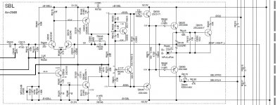
With 4.6V across emitters, suggest work back checking voltages at transistor bases until you find a normal/expected voltage. Check Q6035, 6045. Second thought, maybe measure either side of R5135 to GND, repeat for R5205, these more or less connect to base of Q's. Might come back to Q5045 failed open?
So across both R5135 and R5205 (individually) I only get 12K. And no evidence of charging a cap. I can see there's a parallel path through R6055, R6015, R6055, and R6035, and that does SEEM like the 12K is reasonable, I think? Though maybe not if I'm measuring them individually as opposed to singularly.
Measuring the same circuit on the other channels start out around 12K but I can see the charging as it climes to over 13.5K.
Seems like I'm gonna be stuck pulling the board. Which complicates testing, sadly, but will make it work. Will also check the base's of the transistors.
Measuring the same circuit on the other channels start out around 12K but I can see the charging as it climes to over 13.5K.
Seems like I'm gonna be stuck pulling the board. Which complicates testing, sadly, but will make it work. Will also check the base's of the transistors.
Holy hell the soldering on these amps is awful (and the heat cycling doesn't help). I've found so many joins that look cracked/dry, and a few that definitely were...
Slowly going through and fixing them all, but not sure that would cause this. I'm not seeing any base voltages at all when I'm checking down the line and the unit briefly powers up. =/ which makes me think the output transistors are bad... or I'm missing something super obvious.
Slowly going through and fixing them all, but not sure that would cause this. I'm not seeing any base voltages at all when I'm checking down the line and the unit briefly powers up. =/ which makes me think the output transistors are bad... or I'm missing something super obvious.
Trying to make sense on my last post re:R5315. The idea was to measure transistor base voltages at drivers and then work back until you find an expected voltage as per the schematic. So, need to measure Vdc to CND at Q6035base. Repeat for Q6045b, expect +/- 1.2Vdc. Suggest diode check Q5045(? schematic not real clear, emitter connects to R5175)
Also measure Vdc Q5045 b/c/e to GND
Also measure Vdc Q5045 b/c/e to GND
Thanks! So, none of them are right all the way back to Q5055.
All are base to ground vdc. All are also best guess since the unit only powers up for about 3/4th second. So nothing is stable. Can fire up my scope if we need quicker values.
Q6035: 3.8V
Q6045: -3.8V
Q6015: 4V
Q5035: 11.3V
Q5045: -11.3V
Q5055: -11.3V
Q5045 diode check (pos on left, neg on right):
B-E .6V
B-C .6V
E-B .56V
E-C .689V
C-E OL
C-B OL
Q5045 to ground:
E-GND: -12V (maxes briefly at -14V)
B-GND: -12V
C-GND: -3.9V
Voltages appear mostly symmetrical, eg, Q6035b, Q6045b +/-3.8V.
Q6015b=4V appears to be the odd man out, wondering if that timmer(R6045) is ok. Check solder connections on trimmer and Q6015, diode test this Q.
Q6015b=4V appears to be the odd man out, wondering if that timmer(R6045) is ok. Check solder connections on trimmer and Q6015, diode test this Q.
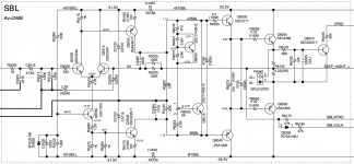
The schematic in post #7 is much better, thanks.
Assume that you diode tested Q6045 in circuit, the abnormal results due to alternate paths?
Assume that you diode tested Q6045 in circuit, the abnormal results due to alternate paths?
Voltages appear mostly symmetrical, eg, Q6035b, Q6045b +/-3.8V.
Q6015b=4V appears to be the odd man out, wondering if that timmer(R6045) is ok. Check solder connections on trimmer and Q6015, diode test this Q.
I'm guessing it's 3.8V like the others, since the unit only powers up briefly, my 87V is having a hard time catching the voltage. Will test again with that one.
I can also pop them out of circuit and test. I believe I recall checking trimmer previously, but will check again.
R6075? I'd consider either Q6035 or Q6045 as suspect. They may test ok on a cheap tester requiring a few volts to fail. Though I'm still thinking that +4V on Q6015b is odd. Along with trimmer, also check R6065. Such troubleshooting is only a guess since could be start up transients etc... have you tried power up on a dim bulb tester?Found the emitter resistor on one of the drivers was blown (open, should be 100R)..
Hi @mbz,
Will check those over the weekend. And yeah, R6075 was open.
I don't have a dim bulb tester... just a Sencore 570 so I set the trip current. It doesn't trip at 4A limit.
I'll also try pulling the questionable guys.
Will check those over the weekend. And yeah, R6075 was open.
I don't have a dim bulb tester... just a Sencore 570 so I set the trip current. It doesn't trip at 4A limit.
I'll also try pulling the questionable guys.
Finally got to this. Pulled all three transistors in question. Q6035 and Q6045 seem okay. Both hFe 165 or so. Actually amazingly matched.
Q6015 has at least a shorted base/collector. My transistor tester doesn’t see it at all, and a diode test shows those two shorted in both directions. So have some replacements on order.
Thanks!
Q6015 has at least a shorted base/collector. My transistor tester doesn’t see it at all, and a diode test shows those two shorted in both directions. So have some replacements on order.
Thanks!
- Home
- Amplifiers
- Solid State
- Repair Onkyo SR508