hi all
I'm building a little 10 watt stereo chipamp, nothing complicated or spectacular, purely as a learning exercise.
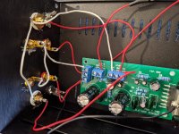
The amp board has 3-way screw terminals for both input and output. The input terminal has Input 1, Input 2, and a ground, the output terminal has Output 1, Output 2, and a ground.
I'm slightly confused as to how I wire up my connections to these. At the moment I have connected the positive of the L and R channel RCA jacks to each of the inputs (L to input 1, R to input 2). The grounds of both RCA jacks are connected together, and a wire from this is connected to the input ground terminal.
I have connected the negative terminals of L + R binding posts together, and connected this to the Output ground terminal. The positive of the L binding post goes to Output 1, and the positive of the R binding post goes to Output 2.
But this doesn't sound right, it sounds like I've wired it out of phase, and the right channel is much louder than the left. And I'm getting a lot of popping and buzzing (which may be just because I haven't yet dressed or shielded the cables). I haven't grounded either the RCAs or the speaker cables to the chassis, and I'm not sure if I should.
A picture is worth a thousand words, the attachment hopefully makes clear what I'm talking about.
Please don't laugh, I know this is basic stuff, but we all have to start somewhere.
Thanks!
I'm building a little 10 watt stereo chipamp, nothing complicated or spectacular, purely as a learning exercise.
The amp board has 3-way screw terminals for both input and output. The input terminal has Input 1, Input 2, and a ground, the output terminal has Output 1, Output 2, and a ground.
I'm slightly confused as to how I wire up my connections to these. At the moment I have connected the positive of the L and R channel RCA jacks to each of the inputs (L to input 1, R to input 2). The grounds of both RCA jacks are connected together, and a wire from this is connected to the input ground terminal.
I have connected the negative terminals of L + R binding posts together, and connected this to the Output ground terminal. The positive of the L binding post goes to Output 1, and the positive of the R binding post goes to Output 2.
But this doesn't sound right, it sounds like I've wired it out of phase, and the right channel is much louder than the left. And I'm getting a lot of popping and buzzing (which may be just because I haven't yet dressed or shielded the cables). I haven't grounded either the RCAs or the speaker cables to the chassis, and I'm not sure if I should.
A picture is worth a thousand words, the attachment hopefully makes clear what I'm talking about.
Please don't laugh, I know this is basic stuff, but we all have to start somewhere.
Thanks!
Attachments
What about the power supply? The connections seem right, as the TDA 2009 is single ended ( no Bridge Tied Load, where the minus is separate for each speaker ).
Try to bring the PSU very close to the amplifier. The supply cap should be close to +V input...I'd say to put it near the chip instead of that 100 uF supply decoupling cap. Also the diode bridge( the rectifier) should be close to the supply cap...yes, everything must be kept tight & compact!
Try to bring the PSU very close to the amplifier. The supply cap should be close to +V input...I'd say to put it near the chip instead of that 100 uF supply decoupling cap. Also the diode bridge( the rectifier) should be close to the supply cap...yes, everything must be kept tight & compact!
Thanks for the reply. Power at the moment is just a 12v DC wallwart. If you think my connections look right I'll do some tidying, and check the soldering again. I was mostly unsure as to whether I had the ground connections correct, but thanks for confirming that it seems I have.
Looks like the channel imbalance is down to a solder joint on the left binding post. Phew. Now I just need to sort out dressing and shielding the wiring properly and see if that reduces noise. Thanks for the help.
I would expect all the power supply and speaker terminals to be close to the chipamp, and the input section at the other side of the board well away from output signals... And I see the ground wire going to the chipamp tab rather than the screwterm - is this a symptom of poor
pcb grounding layout?
pcb grounding layout?
All now working, and sounding good. The power ground to.the chip screw is suggested in the build instructions for the kit as a better grounding scheme. It's a very cheap lot so I wouldn't expect it to be the best design. It sounds very good now it's finished. And no noise problems any more.
I can see this being a really helpful forum. Am about to embark on building something more complex, the experience bfrom this build has been very helpful.
I can see this being a really helpful forum. Am about to embark on building something more complex, the experience bfrom this build has been very helpful.
All now working, and sounding good.

Welcome to the addiction.I can see this being a really helpful forum. Am about to embark on building something more complex, the experience bfrom this build has been very helpful.
the TDA 2009 is single ended ( no Bridge Tied Load, where the minus is separate for each speaker )
Well, of course the chip is not single ended! I mean, amplifiers with just a power transistor/fet work at class A 😱🙄
It uses two NPN in the output stage!
Sorry...😛
- Home
- Amplifiers
- Solid State
- Newbie question about RCA and speaker connections