Hi .... I’m looking for some advice ( “don’t do it “ is not an option ) 
Some background ..
My current Audio system consists of Audio Innovations second Audio Monoblocks , with Bp PSU’s , fed by an Audio Innovations series 1000 pre amp , and SUT .. .. my system sounds great to me ... and I have been over the moon with it for the last 8 years .. but I want to build something myself.. it must sound as good , preferably better than My current system and have a visual impact .. so ...
I am thinking of another SE set up , with a separate PSU based around valve rectification ..
I have a pair of NOS 866a MVT Which I want to pair with 2 x 6ax4’s , this will give the visual impact ( well aware of the pitfalls of MVT’S )
Then on to the amp based on 300b’s .. . .
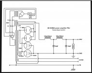
There are lots of amp schematics out there to use , it I cannot find a PSU schematic based on 866a’s ..
Has only one got anything they can share please ?
Cheers Brian
Some background ..
My current Audio system consists of Audio Innovations second Audio Monoblocks , with Bp PSU’s , fed by an Audio Innovations series 1000 pre amp , and SUT .. .. my system sounds great to me ... and I have been over the moon with it for the last 8 years .. but I want to build something myself.. it must sound as good , preferably better than My current system and have a visual impact .. so ...
I am thinking of another SE set up , with a separate PSU based around valve rectification ..
I have a pair of NOS 866a MVT Which I want to pair with 2 x 6ax4’s , this will give the visual impact ( well aware of the pitfalls of MVT’S )
Then on to the amp based on 300b’s .. . .
There are lots of amp schematics out there to use , it I cannot find a PSU schematic based on 866a’s ..
Has only one got anything they can share please ?
Cheers Brian
Check out Thomas Mayers ”Vinylsavor” blog. There are a couple of schematics for PSU:s with the 866a MVT there.
Hi , thanks for the reply , yes I have that one but there’s info missing .. and I don’t have the knowledge to workout what is required ..
And I’m well aware of the results if mistakes are made ..
If someone can help me fill in the blank space so to speak that would be great 👍
And I’m well aware of the results if mistakes are made ..
If someone can help me fill in the blank space so to speak that would be great 👍
Read some of the data sheets and old ARRL books. They have good explanations on using mercury rectifiers.
If you want to use 866s, you will need to work out a time delay or manual switching to allow the 866s to warm up before anything else in the amp is turned on. You might be able to use the 6AX4s as full wave rectifiers in your power supply, then use the 866s as a series pass device, though they won't really do much in that application. The 6AX4 and an NTC thermistor or two will give you a very slow, controlled warm up time to protect the 866s.
Another option that I have used is to provide a rotary switch for the power switch with three positions. The first position is off, the next position only heats the 866s, and the last position turns everything on.
Lastly you could get a time delay relay kit and put a 60 second delay in to close the connection to the CT after some warm up time.
Most people would advise against using MV rectifiers. You will need to enclose the power supply in a faraday cage to avoid nasty RF, and you might want a UV filter, too. You can get a tan / eye damage from them apparently.
Definitely heed the Hg vapor warnings. You might use metal window screening for the Faraday cage. Most of the desired visual impact will be retained.
A pair of 6AX4s and a pair of 866s, whose filament voltages are different, strongly suggests a bridge rectifier to me.
An Octal Amperite thermal relay paired with an Octal plug in DPDT mechanical relay will give you a non-SS time delay for the Hg vapor tubes to get hot. "EBone" is where to get the Amperite part. The parts supply houses' price for glass envelope Amperite relays is high.
FWIW, the visual impact idea could be carried further by the use of gas discharge tube regulated B+ in the small signal circuitry.
Last edited:
When using Amperite time delays, remember that it will take nn seconds for the contacts to make contact. But it will take about the same nn seconds before the contact is released. So if the power supply is switched ON and than OFF, make sure you wait the nn seconds yourself, before switching it back ON. Otherwise the delay is shortened, what could cause damage to your circuits.
I added a relay, that will bridge the contacts and switch off the heating of the Amperite delay.
Regards, Gerrit
I added a relay, that will bridge the contacts and switch off the heating of the Amperite delay.
Regards, Gerrit
At a minimum I would have two delays. One to heat the filaments for a few minutes and then one to short out a soft start resistor right after the tubes. The manuals even recommend chokes before the plates to filter RF hash.
When using 866A tubes use swing chokes in a LC or LCLC filter configuration.
Look for a Triad C20A or C22A on ebay. Caps I have seen used are around 20uf, seems kind low to me, by today's standards, but these tubes were used a long time ago. I bet in the day these were very expensive. Now it's the swing chokes that will drive the cost. I have see C20A which I think is 6H go for $100. The C22A is 10H? but I have yet to see one available.
Look for a Triad C20A or C22A on ebay. Caps I have seen used are around 20uf, seems kind low to me, by today's standards, but these tubes were used a long time ago. I bet in the day these were very expensive. Now it's the swing chokes that will drive the cost. I have see C20A which I think is 6H go for $100. The C22A is 10H? but I have yet to see one available.
When using Amperite time delays, remember that it will take nn seconds for the contacts to make contact. But it will take about the same nn seconds before the contact is released. So if the power supply is switched ON and than OFF, make sure you wait the nn seconds yourself, before switching it back ON. Otherwise the delay is shortened, what could cause damage to your circuits.
I added a relay, that will bridge the contacts and switch off the heating of the Amperite delay.
Regards, Gerrit
The characteristics of Amperite thermal delay relays are exactly why I suggest pairing them with DPDT mechanical relays.
One pole of the mechanical relay controls the audio circuitry's PSU. The normally closed contact of the mechanical relay's 2nd pole applies power to the thermal relay's heater. The normally open contact of that 2nd pole is wired in a self latching configuration. When power is applied to the composite, the thermal relay heats up and its contacts close. That applies power to the coil of the mechanical relay, which latches. The audio circuitry is energized and power is removed from the thermal relay's heater. Therefore, the thermal relay immediately starts to cool down, which restores the time delay characteristic and also promotes long part life.
Opening the manually operated power switch resets the composite to the idle state.
Looks good.
I — personally — would leave the 6AX4 valves 'not hooked in' except with live heaters. Just for show. I'd use a series-balanced pair of silicon rectifiers to complete the full-wave bridge.
Nothing else in circuit changes.
Output voltage perhaps 5% higher overall. No issues with the breakdown insulation of the 6.3 VAC winding, that way. Moreover, the spare 6.3 might prove more useful in your monoblock implementation.
⋅-⋅-⋅ Just saying, ⋅-⋅-⋅
⋅-=≡ GoatGuy ✓ ≡=-⋅
Depending on just what tubes you have there is a caution. The older tubes by makers like RCA, Sylvania and a couple of others have a coating on the elements that when heated can flake off. These will be the larger (full size) size 866's. The slightly smaller style, like the GE's, seems to be free of this condition. Their plates will be shiny metal compared to the dark (sometimes orange peel) coating on the older versions. When this coating comes off it will short the tube. If in doubt of what you have, power them up (2.5V) and run in series with an incandescent lamp to get them hot.I have a pair of NOS 866a MVT...
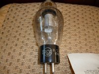
Those are pretty old and the plate has a black coating that will quite probably come off when hot. Not every single one, but most do this. Most sellers don't test these. And regular testers don't make the tube hot enough with a quick emission test. If you can run power through the tube and watch the plate as it heats up, you can see it happen. Once off if the flakes are kept at the bottom of the tube they'll be OK. Assuming they are kept vertical. Those tubes could be more then sixty years old. Before using them in a PS, run them with a load and get them hot for a preliminary safety test. This comes from years of experience.
Besides the visual spectacle, I am expecting substantially lowered distortion compared to silicon diodes.
Those are pretty old and the plate has a black coating that will quite probably come off when hot. Not every single one, but most do this. Most sellers don't test these. And regular testers don't make the tube hot enough with a quick emission test. If you can run power through the tube and watch the plate as it heats up, you can see it happen. Once off if the flakes are kept at the bottom of the tube they'll be OK. Assuming they are kept vertical. Those tubes could be more then sixty years old. Before using them in a PS, run them with a load and get them hot for a preliminary safety test. This comes from years of experience.
Thanks for the info , was going to power up the heaters , but how would you run them with load ???
Last edited:
- Home
- Amplifiers
- Tubes / Valves
- Tube rectified PSU