Hi,
I am happy to be a part of DIY Audio! This is my first post. Apologize if my posting is not perfect.
I am developing a 2 and 2.1 channel remote controller kit using PT2314 and ATMEGA328. PT2314 is absolutely amazing audio processor with 4 inputs, bass & treble controller and I2C/IIC communication.
The amplifier which I am using for testing purpose is a Class D amplifier which runs in 12V.
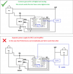
When I power up the amplifier and the audio processor circuit with the same power supply and with common ground, the audio processor circuit works fine without issues except for some digital circuit noise.
But when I power up with different power supplies for the audio processor circuit and the amplifier, the PT2314 becomes very hot and fails then on. In this case the the analog and digital ground are isolated. I am not sure if this isolated ground connection creates the problem. But I am sure there is a specific purpose the analog and digital ground are separated by the IC manufacturer.
Please find the pictures attached for the connections made. I sorry for the bad picture.
Anyone please suggest how to make this circuit work with different power supply for amplifier and audio processor / controller circuit.
Thanks,
DMA
I am happy to be a part of DIY Audio! This is my first post. Apologize if my posting is not perfect.
I am developing a 2 and 2.1 channel remote controller kit using PT2314 and ATMEGA328. PT2314 is absolutely amazing audio processor with 4 inputs, bass & treble controller and I2C/IIC communication.
The amplifier which I am using for testing purpose is a Class D amplifier which runs in 12V.
When I power up the amplifier and the audio processor circuit with the same power supply and with common ground, the audio processor circuit works fine without issues except for some digital circuit noise.
But when I power up with different power supplies for the audio processor circuit and the amplifier, the PT2314 becomes very hot and fails then on. In this case the the analog and digital ground are isolated. I am not sure if this isolated ground connection creates the problem. But I am sure there is a specific purpose the analog and digital ground are separated by the IC manufacturer.
Please find the pictures attached for the connections made. I sorry for the bad picture.
Anyone please suggest how to make this circuit work with different power supply for amplifier and audio processor / controller circuit.
Thanks,
DMA
Attachments
I presume AGND & VGND must be connected.
Thanks for the immediate reply. I will try that.
But, if i connect the AGND and DGND in the PT2314, then the audio out will need to be connected to the amplifier's AGND right? If so, will it not have any digital noise? The purpose of having AGND and DGND separate by the IC is not defeated?
Thanks,
DMA
They still have to be connected. They're both defined to be at 0V potential.
Think analog ground = clean ground, and digital ground = dirty ground.
You deal with this by the pcb layout design.
Think analog ground = clean ground, and digital ground = dirty ground.
You deal with this by the pcb layout design.
Last edited:
They still have to be connected. They're both defined to be at 0V potential.
Think analog ground = clean ground, and digital ground = dirty ground.
You deal with this by the pcb layout design.
Thanks for the advice. I will do as you all suggested and post the result as soon as possible.
Cheers,
DMA
Normally the grounds are deliberately separate to keep digital hash out of the analog section. However they must be within a few 100mV of each other at all times, and usually the supply rails for digital and analog need to be present simultaneously too.
Back-to-back schottky diodes allow the grounds to be connected so that the chip isn't going to fry, without injecting noise into the analog side, and typically the actual signal connection between the grounds is done via filtering (RC or LC).
Normally you have to give thought to the power supply arrangements to ensure both digital and analog supplies are presented together, cannot stray apart from each other, but that the digital supply rail and ground don't directly inject noise to the analog counterparts.
Thanks for your input. Sure, i will try the RC or LC filters in the power supply and handle the pcb layout design to handle the grounds when connecting the digital and analog..
Cheers,
DMA
Cheers,
DMA
- Home
- Source & Line
- Analog Line Level
- PT2314 burns out when power supply is isolated