Dear brains.
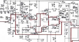
A friend of mine has asked me to take a look at his Nad 705 receiver that refuse to leave protection when powered on. I found the reason for this being 13VDC on the left channel output.
I can measure and solder, but my engineering-skills are pretty non-existing, so before I start destroying the board with experiments, I would be very grateful if you guys would take a look at my findings.
No magic smoke has been released, and nothing seems to get too hot when left powered on.
All other voltages than the ones written in red, are spot-on.
If I was to take a stab at the problem, I would think that Q107 was dead in an 'open' state, but as this is close to being a clean guess, please let me know if I'm wrong.
Thank you very much for your time.
Attachments
You wouldn't be too far out as the high voltages start earlier in the circuit and no burnt out/blackened components (due to high current) farther on.
Don,t know about "open-state " as you suggest more like short circuit.
Without disconnecting anything using your ohmmeter section of your multi-meter measure across the Emitter/Collector of both Q107 & Q109 for a DEAD short .
If that does not produce anything considering the fact of lack of knowledge and equipment then use the old fashioned test --better seen on an analogue meter of putting the Positive meter probe on the PNP Q107 BASE and test for a reading using the Negative probe between the base and collector and emitter.
Put the the Negative probe on the base of Q109 NPN BASE and test for a reading between the collector and emitter .
There should NOT be a short circuit just a low reading .
That,s a start if they are okay get back .
Hello Duncan.
Thank you very much for your reply.
I have done the measurements you suggested, and found no shorts anywhere.
My main fear was that the problem could be located somewhere else though.
I have no problem changing both Q107 and Q109 just to be sure.
I guess the next step will be to remove both, and test them out of circuit!
If you are using your digital meter to test the transistors then reverse the probes I mentioned as it only applies to an analogue meter.
Is Q103 included in the faulty readings ?
If you get faulty readings near the input its not likely to be caused by faults in the output .
Is Q103 included in the faulty readings ?
If you get faulty readings near the input its not likely to be caused by faults in the output .
Suggest use your multimeters diode function to test transistors, test in both directions/6 combinations. Does look like either Q107 (replace with KSA992) or Q109 as prime candidates.
Thats why I use an analogue meter to test BJT,s, bigger current applied , I presumed the OP knew this .
Thank you very much guys.
I have ordered both Q107 and Q109, just to be safe. I will desolder and report back as soon as they're in the house.
🙂
I have ordered both Q107 and Q109, just to be safe. I will desolder and report back as soon as they're in the house.
🙂
Parts arrived today.
Removed Q107 and Q109. Both measured ok, but I changed them anyway.
This, of course, changed absolutely nothing.
🙁
Removed Q107 and Q109. Both measured ok, but I changed them anyway.
This, of course, changed absolutely nothing.
🙁
- Home
- Amplifiers
- Solid State
- NAD 705 in protection