I've never tried but I image you could model it as a back loaded horn. It certainly looks like one!
How do I model a port that is flared in both ends (e.g. aeroport) for a simple bass reflex enclosure in Hornresp
Attachments
Brilliant - thanks David! Sometimes it's best to hear it straight from the horse's mouth 😀
So here is a comparison between a straight and a flared port. First, the straight port:


Second, the flared port:


A couple of observations:
1. The port tuning is different. The flared port has a higher tuning as if it is net shorter. This is consistent with the rule of thumb that only half the flare length should be counted as effective tube length. I will shorten the straight vent by 89mm (2 x 89/2) or whatever it takes to match the tuning of the flared port.
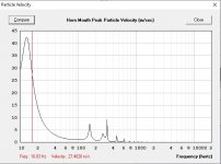
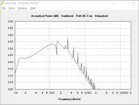
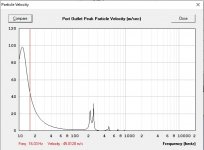
2. The port velocity is reduced in the flared port, as expected and intended.
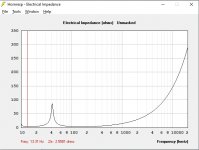
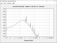
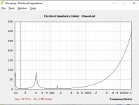
3. The flared port has a resonance at 155-160Hz, as can be seen from the FR and impedance plots, which the straight port does not have. Not sure how accurate this is, especially since the flared port has a radius flare rather than a cone as modeled.
4. Atc for the flared port model is probably wrong since I am not entirely clear on how to calculate this exactly for my enclsoure.
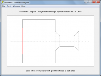
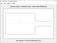
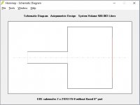
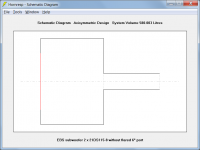
5. The modeled port is round and 8" (187.6mm inner diameter), and not 6" like it says in the pics above, with a 3.5" (89mm) long flare (Aeroport) in each end extending out to 12" (302mm inner diameter), like this:

So definitely worthwhile to model the flares to confirm lower port velocities. Thanks again, David 🙂
So here is a comparison between a straight and a flared port. First, the straight port:
Second, the flared port:
A couple of observations:
1. The port tuning is different. The flared port has a higher tuning as if it is net shorter. This is consistent with the rule of thumb that only half the flare length should be counted as effective tube length. I will shorten the straight vent by 89mm (2 x 89/2) or whatever it takes to match the tuning of the flared port.
2. The port velocity is reduced in the flared port, as expected and intended.
3. The flared port has a resonance at 155-160Hz, as can be seen from the FR and impedance plots, which the straight port does not have. Not sure how accurate this is, especially since the flared port has a radius flare rather than a cone as modeled.
4. Atc for the flared port model is probably wrong since I am not entirely clear on how to calculate this exactly for my enclsoure.
5. The modeled port is round and 8" (187.6mm inner diameter), and not 6" like it says in the pics above, with a 3.5" (89mm) long flare (Aeroport) in each end extending out to 12" (302mm inner diameter), like this:
So definitely worthwhile to model the flares to confirm lower port velocities. Thanks again, David 🙂
Attachments
-
 HR aeroport 04.jpg60.4 KB · Views: 900
 -
 HR aeroport 03.jpg63.8 KB · Views: 891
 -
 HR aeroport 02.jpg39.9 KB · Views: 976
 -
 HR aeroport 01.jpg81.6 KB · Views: 933
 -
 HR aeroport 10.jpg60.8 KB · Views: 945
 -
 HR aeroport 09.jpg54 KB · Views: 938
 -
 HR aeroport 08.jpg64.3 KB · Views: 918
 -
 HR aeroport 07.jpg38.6 KB · Views: 947
 -
 HR aeroport 06.jpg84.5 KB · Views: 969
 -
 HR aeroport 05.jpg59.8 KB · Views: 922
Hi InOtIn,
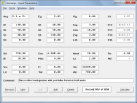
Just be aware that when a cylindrical port tube is specified using Ap and Lpt, Hornresp assumes that a Helmholtz resonator type system is being modelled, and automatically includes an internal end correction. (An end correction is not required at the external end because the radiation impedance is being taken into account). For your 'straight vent' example, the effective tube length therefore becomes 64.30 cm plus an internal end correction of 5.75 cm.
When the port tube is specified using horn segments, as is the case for your 'flared port' example, Hornresp does not know to include an end correction at the horn throat.
(If you specify your straight vent example as shown in the attachments below, the internal end correction will not be included, and you can see what difference there is from your original straight vent results).
Not a problem, glad to be able to help out 🙂.
Kind regards,
David
1. The port tuning is different. The flared port has a higher tuning as if it is net shorter. This is consistent with the rule of thumb that only half the flare length should be counted as effective tube length. I will shorten the straight vent by 89mm (2 x 89/2) or whatever it takes to match the tuning of the flared port.
Just be aware that when a cylindrical port tube is specified using Ap and Lpt, Hornresp assumes that a Helmholtz resonator type system is being modelled, and automatically includes an internal end correction. (An end correction is not required at the external end because the radiation impedance is being taken into account). For your 'straight vent' example, the effective tube length therefore becomes 64.30 cm plus an internal end correction of 5.75 cm.
When the port tube is specified using horn segments, as is the case for your 'flared port' example, Hornresp does not know to include an end correction at the horn throat.
(If you specify your straight vent example as shown in the attachments below, the internal end correction will not be included, and you can see what difference there is from your original straight vent results).
Thanks again, David 🙂
Not a problem, glad to be able to help out 🙂.
Kind regards,
David
Attachments
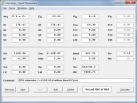
Just be aware that when a cylindrical port tube is specified using Ap and Lpt, Hornresp assumes that a Helmholtz resonator type system is being modelled, and automatically includes an internal end correction. (An end correction is not required at the external end because the radiation impedance is being taken into account). For your 'straight vent' example, the effective tube length therefore becomes 64.30 cm plus an internal end correction of 5.75 cm.
When the port tube is specified using horn segments, as is the case for your 'flared port' example, Hornresp does not know to include an end correction at the horn throat.
(If you specify your straight vent example as shown in the attachments below, the internal end correction will not be included, and you can see what difference there is from your original straight vent results).
Great info - thanks, David!
When I use your value for Atc as well, the port resonance at 155-160 Hz disappears. Would you mind telling me how I should go about calculating Atc for a plain-vanilla bass reflex enclosure, please?
Hi InOtIn,
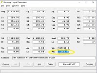
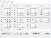
Strictly speaking, the resonance spike you are seeing in the electrical impedance is due to the chamber rather than the port. In your 'flared port' example you set Vtc = 559311.0 cm^3 and Atc = 5000.00 cm^2, which means that the chamber has a depth of Vtc / Atc = 559311 / 5000 = 111.86 cm, or half a wavelength at 153.76 Hz, assuming the velocity of sound is 344 m/sec.
In my case, because I wanted the comparison to be as accurate as possible, I set my 'flared port' chamber dimensions to be the same as those of your original 'straight port' chamber. Your values of Vrc = 562.23 litres and Lrc = 72.00 cm became Vtc = 562.23 * 1000 = 562230.0 cm^3 and Atc = Vrc / Lrc = 562230 / 72 = 7808.75 cm^2 in my example. Because my chamber has a depth of 72.00 cm rather than the value of 111.86 cm used in your example, the half-wavelength resonance shifts from 153.76 Hz up to 238.89 Hz. The chamber resonance is still there, but is less noticeable at the higher frequency. (It can be removed completely from the simulation results if you like, by selecting the 'resonances masked' option).
Decide on the chamber volume you want, and the distance from the rear of the driver diaphragm to the back panel of the cabinet (ie the depth), then divide the volume by the depth to determine Atc.
Kind regards,
David
When I use your value for Atc as well, the port resonance at 155-160 Hz disappears.
Strictly speaking, the resonance spike you are seeing in the electrical impedance is due to the chamber rather than the port. In your 'flared port' example you set Vtc = 559311.0 cm^3 and Atc = 5000.00 cm^2, which means that the chamber has a depth of Vtc / Atc = 559311 / 5000 = 111.86 cm, or half a wavelength at 153.76 Hz, assuming the velocity of sound is 344 m/sec.
In my case, because I wanted the comparison to be as accurate as possible, I set my 'flared port' chamber dimensions to be the same as those of your original 'straight port' chamber. Your values of Vrc = 562.23 litres and Lrc = 72.00 cm became Vtc = 562.23 * 1000 = 562230.0 cm^3 and Atc = Vrc / Lrc = 562230 / 72 = 7808.75 cm^2 in my example. Because my chamber has a depth of 72.00 cm rather than the value of 111.86 cm used in your example, the half-wavelength resonance shifts from 153.76 Hz up to 238.89 Hz. The chamber resonance is still there, but is less noticeable at the higher frequency. (It can be removed completely from the simulation results if you like, by selecting the 'resonances masked' option).
Would you mind telling me how I should go about calculating Atc for a plain-vanilla bass reflex enclosure, please?
Decide on the chamber volume you want, and the distance from the rear of the driver diaphragm to the back panel of the cabinet (ie the depth), then divide the volume by the depth to determine Atc.
Kind regards,
David
Thank you David for taking the time to explain this in detail, much appreciated.
So Atc = Vtc/Lrc.... DUH! I had been led to believe its calculation involved estimating the chamber’s equivalent cylinder volume and diameter etc so had over complicated it. Thanks for saving me time in the future.
So me inadvertently using 111.86 as Lrc instead of 72.00 would of course create the 153.76 Hz chamber resonance, makes perfect sense. 😱
Now if I could just figure out how to identify the first port resonance...
Last edited:
Question, is that simple geometry of the flare itself integrated into the soft-wares' calculations? I see a simple change in angle from the port walls to the first & only increase in port diameter...would not this sharp change induce turbulent flow?...a stalling of flow with the likes of boundary separations & possible vortices?
I always thought a one-quarter radius was optimal...now the size of this curvature (port diameter?)....I just don't know.
I did read somewhere, halfway thru this radius is our "starting point" to measure port length.
------------------Rick......
I always thought a one-quarter radius was optimal...now the size of this curvature (port diameter?)....I just don't know.
I did read somewhere, halfway thru this radius is our "starting point" to measure port length.
------------------Rick......
Rick, in my case the port actually has a radius and not a cone-type of flare:
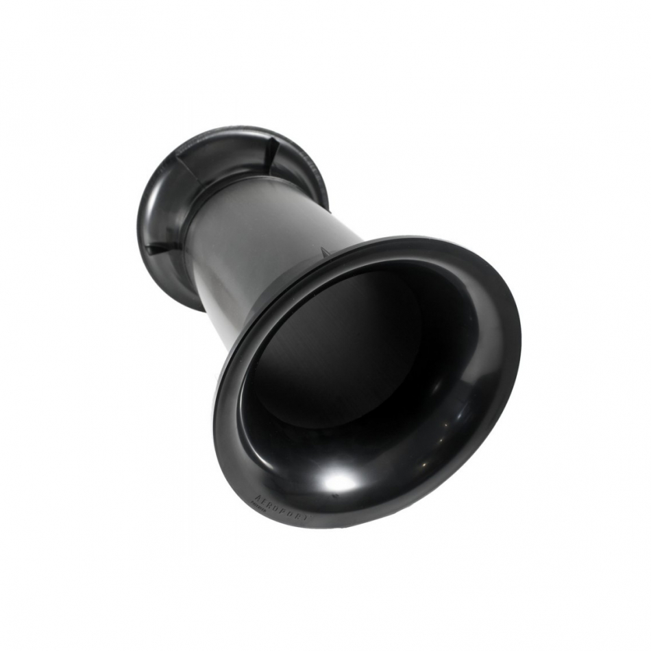
Perhaps the radius could be modelled in HR as well (exponential instead of conical) but I wouldn't know how...
Perhaps the radius could be modelled in HR as well (exponential instead of conical) but I wouldn't know how...
Hi InOtIn,
For the case we were considering yes, because for comparison purposes we wanted the throat chamber to have the same dimensions as the rear chamber.
The equation relating specifically to the throat chamber is actually Atc = Vtc / Ltc, where Ltc is the throat chamber length. Alternatively, Ltc = Vtc / Atc.
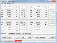
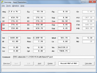
If the mouse pointer is moved over either the Vtc or Atc labels or text boxes, the value of Ltc is given in the status bar panel at the bottom of the Input Parameters window, as shown in Attachment 1.
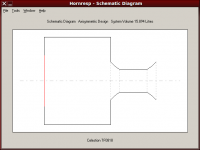
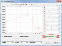
Open the Loudspeaker Wizard, double-click on any of the charts, then move the mouse pointer over the vertical green marker line to display the fundamental frequency of the system, as shown in Attachment 2.
Kind regards,
David
So Atc = Vtc/Lrc....
For the case we were considering yes, because for comparison purposes we wanted the throat chamber to have the same dimensions as the rear chamber.
The equation relating specifically to the throat chamber is actually Atc = Vtc / Ltc, where Ltc is the throat chamber length. Alternatively, Ltc = Vtc / Atc.
If the mouse pointer is moved over either the Vtc or Atc labels or text boxes, the value of Ltc is given in the status bar panel at the bottom of the Input Parameters window, as shown in Attachment 1.
Now if I could just figure out how to identify the first port resonance...
Open the Loudspeaker Wizard, double-click on any of the charts, then move the mouse pointer over the vertical green marker line to display the fundamental frequency of the system, as shown in Attachment 2.
Kind regards,
David
Attachments
Last edited:
Perhaps the radius could be modelled in HR as well
Not if there are multiple segments.
Changing the flare profiles at the ends of the port tube will make no practical difference to the Hornresp results. This can be readily demonstrated by switching the flares from Exp to Con or Par. As a further example, the port tube exit flare in the attachment has been modified to more closely approximate a radius bend, by using two segments. The results remain effectively the same.
Attachments
- Home
- Loudspeakers
- Multi-Way
- Hornresp - how model flared port?