Hi,
I have been building and testing a small SET amp which I plan to use for background musak in my man cave, aka "the shed".
I started this thread:
6P6S triode strapped output stage: first pass experiments.
But since I started, it has developed and moved on past a first pass experiment - so I am starting this thread to collate all the information I have collected, measurements I have taken, schematics etc.
I would also openly welcome constructive criticism, as there are a couple of niggles which may or may not be important.
Please find the attached:
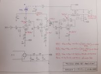
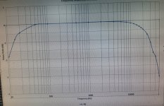
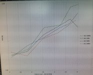
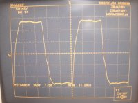
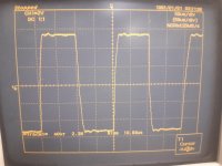
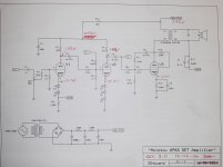
Schematic, frequency response, THD at 4 frequencies (100Hz, 1k, 5k 10k) and a couple of shots of the square wave response (5k and 10k)
I have taken measures for output impedance at 1kHz, and dV/dI = 1.05 Ohms...
this is much better than I expected!
I have been building and testing a small SET amp which I plan to use for background musak in my man cave, aka "the shed".
I started this thread:
6P6S triode strapped output stage: first pass experiments.
But since I started, it has developed and moved on past a first pass experiment - so I am starting this thread to collate all the information I have collected, measurements I have taken, schematics etc.
I would also openly welcome constructive criticism, as there are a couple of niggles which may or may not be important.
Please find the attached:
Schematic, frequency response, THD at 4 frequencies (100Hz, 1k, 5k 10k) and a couple of shots of the square wave response (5k and 10k)
I have taken measures for output impedance at 1kHz, and dV/dI = 1.05 Ohms...
this is much better than I expected!
Attachments
-
 20200612_124010_copy_1551x1141.jpg219.2 KB · Views: 485
 -
 20200612_122050_copy_1746x1125.jpg699.5 KB · Views: 448
 -
 20200612_074956_copy_1511x1225.jpg628.3 KB · Views: 363
 -
 20200612_113936_copy_2304x1728.jpg423.3 KB · Views: 367
 -
 20200612_114002_copy_2304x1728.jpg476.2 KB · Views: 331
 -
 20200426_114828_copy_1843x1382.jpg533.4 KB · Views: 245
Last edited:
In the schematic above, I have shown a different location for the decoupling capacitor, in dashed line.
I havent tried it yet, but I think maybe that location may provide better ripple filtering, being as I can use a lower voltage rated capacitor, and/or increase its size.
Also, I may change the PSU to each of the two preamp stages, so each has it's own RC - but I havent got around to it.
It may be that there is some feedback through the supply rails, that a more isolated HT supply to each triode may improve, or ruin, something.
Lastly, I have my doubts about the secondary feedback to the input stage cathode - it works rather well...but I have my doubts about the very low resistances involved.
Any advice or criticism in these regards is most welcome.
Looks good at a glance (I'm at work and skimmed through your linked thread) but some initial thoughts-
Replace D0 with a resistor, and put a capacitor to ground between it and the junction to R14. You'll get more ripple reduction than using a diode(zener) here. Don't worry too much about isolating the feed to each triode, simply isolating each channel from eachother should be plenty.
What triodes are you using up front? I would almost say that dropping less voltage in the filtering and making their plate resistors about 20% larger would be a good idea, assuming they can handle the late voltage.
Initial distortion looks pretty good. 1.7 watts at 2% isn't terrible for a 6V6/6P6S type in SE. I bet if you iron out the front end a bit you might be able to take the edge off even more. Increase the front end plate voltage and load resistance if you can, it should be a simple matter of swapping a few resistors around more or less.
Last edited:
Yays!
I'm glad you stopped by Lingwendil!
I had originally used a simple dropping resistance from the HT to feed the front end- 1N5378 is just very simple to drop 100V, where a resistance would need to be able to supply say 7mA.... 100/0.007 = 14k... I just thought that 14k may just lead to a PSU that is a bit soft, and saggy.
Sure is easy to try and compare though, so I should do it!
Currently in latest schematic in the opening post, I can get practically 2W at 1% or less.
The front end is two stages of 6S6B-V wire ended triode, which I have some great experiences with.
There's something like 20 V/V gain in those two stages, and when I checked the first version of the stages, THD was very low, about 0.5%.
I should revisit that perhaps, but it's pretty clean as is.
If anything I should recheck to confirm the gain of each stage
As usual the output stage and OPT both generate and cancel some harmonics, so in connecting secondary feedback to the input stage I hoped to clean up the power stage. It appears to have worked nicely.
I am unsure that the "global" feedback I have used has any affect on output impedance, but as it stands the power stage has low gain, probably about 3 V/V.
The part that has stunned me is the large impact of the FB to input cathode!
Oh and the output impedance!
I suppose I could use some of the CCS I made for other circuits I have been playing with - my thought at the moment is, if anything, a CCS under the 6P6S might have the largest impact on linearity.
Can R11 go back to the plate of V2? That should be workable to get rid of a cap. You could aim to optimize this to eliminate the need for GNFB at all.
What does the AC signal look like on the cathode of V1 when the amp is playing a tone?
What does the AC signal look like on the cathode of V1 when the amp is playing a tone?
Audiowize,
Hmm plate to plate feedback?
I admit, I havent ventured to try that...and it should be easy to try out.
I havent looked at the cathode signal, another good idea.
I do know, that measured with a fairly wide band DMM, I measure about 300mV RMS AC 'signal' at the cathode feedback node, when the input is driven with 1V RMS.
So quite a large amount of feedback, maybe 10dB, or is that -10dB, relatively...
Last edited:
Yes, and also local to the grid of the output?
I'm stupid, so are you suggesting I need DC feedback to the driver stage?
I need to read MJ and MB books again and refresh my memory,
As far as raising the front end voltages, as it stands for the 6S6B, max. Anode voltage of 250V, so I could probably take the front end HT up 20% or so, and adjust anode resistors.
Attachments
Last edited:
I hope you are using a power transformer (it was suspiciously missing in your schematic).
Direct operation from the Mains Power is just as dangerous as the name of your amp . . .
Molotov (cocktail).
Safety First!
Prevent the "Surviving Spouse Syndrome", use a proper power transformer.
Other than that, the amplifier looks like a winner.
Good Job!
Reminds me of what they asked Mrs. Lincoln: Other than that Mrs Lincoln, how was the play?
Last edited:
To clarify:
I am using a isolation transformer, fed from a 7A variac.
Actually 230:110 -> 110:230 fed from the variac
Thank you for pointing out what I hadn't considered.
I'll have to edit the OP when I'm back on the other PC.
And thank you. Praise indeed!
I dont think the design is perfected, I could probably change a few capacitor sizes, add grid bypasses of a few pF (that arguably should be there anyway)..
Last edited:
1. Plate to plate DC coupled feedback between output and driver tubes...
I left the global feedback in place, and the local FB around the driver stage.
R11 re-routed to the driver anode, R11 value the same, at 180k.
Very little change to THD, slightly worsened overall, F2 at -25, F at -30dB - probably 0.5 to 1 dBV increase in output.
So then I removed the driver plate to grid FB and used the plate to plate alone, again, using the same value, 180k.
Motor boarding at about 1/4 Hz, accompanied by snivets.
Putting it all back as it was, and THD still looks the best result, using the circuit in post #1
Admittedly I havent tweaked the feedback resistance with the global loop disconnected, so any effect is partially hidden.
When I get some more time, I will try again, with no global loop.
2. The signal at the cathode of the input stage, looks clean, no ugliness - also no FFT taken (yet) - as before, cathode signal amplitude is around 1/3rd of the input to the grid, 0.3V RMS.
Last edited:
Of course, one perceived disadvantage of returning feedback to the input cathode is the change in gain structure.
Where usually, or so I have been told, input stage gain is usually the largest, leaving the driver with less voltage gain to handle/more current driving ability for the next stage.
In this case, input stage gain is now reduced to around 4V/V, driver gain is 8.5V/V, and output gain of 3V/V.
Where usually, or so I have been told, input stage gain is usually the largest, leaving the driver with less voltage gain to handle/more current driving ability for the next stage.
In this case, input stage gain is now reduced to around 4V/V, driver gain is 8.5V/V, and output gain of 3V/V.
i think the values of some of the series capacitors like C1 and C3 are a bit excessive and can be a lot lower.
Also R1 doesn't need to be as high, around 10k is enough, and will result in a little less noise.
If it's just for audio, I would move the volume pot in front of V1 and just simplify the amount of resistors in general.
I could live with diodes on the pre-amp tubes (I don't think it has a significant difference), but using on on the output tube can be sometimes a bit of an issue when changing the and re-biasing again.
the amount of feedback with 620R and 120R is really low
C1 and C3 nay be larger than needed. If I recall I calculated a Fc in single digit Hz.
R1 may be slightly large, but without adding grid bypassing, it may help reject RF - still, I could change it to 22k/25k same as the 2nd stage, easily enough since theres no plate to grid resistor to adjust.
The volume pot is in the best place possible, other than directly before the output stage - volume at the input is about the worst case scenario for noise.
I have been thinking of taking the zener out, and going back to cathode bias in the output stage. Again, easy enough to try, though I expect it will degrade THD slightly.
The amount of feedback, you say, is small- and I thought so too, before measuring the voltage fed back.
The feedback signal is about 1/3rd of the input signal, about -10dB relative to input.
Referred to the output, the feedback signal is about 1/12th.
Coincidentally, this isnt far off 10% cathode feedback (ok so its 8.333%)
Last edited:
Is it, really? Never seen a volume control within the GNFB loop, and it doesn't exactly make sense to me, as the NFB tries to eliminate it's impact. Is there really any issue with noise in a power amplifier? What's it's sensitivity?The volume pot is in the best place possible, other than directly before the output stage - volume at the input is about the worst case scenario for noise.
Best regards!
Well...
I have never built an amplifier with global feedback, nor studied any in detail - however, I have been lead to believe it is better to attenuate a large signal at some point in an amplifier (vol control) rather than attenuate a relatively small signal.
With respect to minimising noise, that is.
I could quite easily move it to the input, I have just been lead to believe it's better practice to control volume between stages, rather than at the input.
I could possibly have been lesd astray. 😀
Tbh Kay,I dont see your point, so I may just have killed one too many brain cells!
Working it through in text here, then deleting to save my modesty....
So yes a vol control there may change the FB ratio at the input stage cathode.
And yknow, I hadnt noticed anything like that....probably as I havent used the volume pot, when testing, other than to check it was wide open.
So...
Thank you Kay. (Also b_force)
I have to admit I couldnt see it, and was trying to reign in my belligerence - worked it through, and yes, you have hit on something.
A glaring error, I'm surprised noone else saw it!
Last edited:
I'm just miffed I didnt try the volume pot in testing, and find the error!
Or even just see it, in my own drawing.

Or even just see it, in my own drawing.
I dont think so, no.
I mean I've made one glaring error, so I could be wrong - but I'm pretty sure I have it correct.
I mean I've made one glaring error, so I could be wrong - but I'm pretty sure I have it correct.
- Home
- Amplifiers
- Tubes / Valves
- 6P6S SET amplifier - looking for constructive criticism.