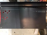
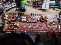
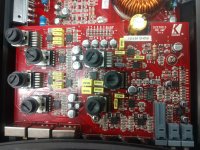
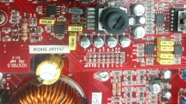
This is a ZX700.5. I'm not sure which version/model year this amp is. Take a picture of the entire board with preamp in place and a close up of the silkscreen showing version date build etc. Also, pictures of the chassis, end panel, cover plate would be helpful. Once I know the model year I will be able to pull the schematics I need to advice.
The 11ZX700.5 has a different arrangement for the +/- 15 volt supply. I recall seeing this a number of times and just needed to be sure I had the right schematic version.
Ra2 is on the input side of U07-KIA7915 -15volt regulator. You will most likely find C524-47uF/16v capacitor on the preamp board is shorted, check and replace if true.
Without the preamp board in place, and any damaged components U07, D29,D30,Ra2,Da1,Ca4 replaced, check to see if you can now power up the amp and if you have -15Vdc across Ca4. If true and C524 replaced and no shorts across the cap, install preamp board and retry.
I removed c524 because on the board it was a direct short but when I took the cap off and tested it it read 47ohms. I replaced it anyway and still have a short on c524 along with c691 right next to it. I also replaced c691
RA2 is 2 watt rated.
When you have replaced RA2, and w/o the preamp board in place check power up amp and measure to see if you have 15Vdc across Ca4.
Most likely one or more of the NJM2060's or NJM2068's is shorted internally. You may be able to narrow it down by systematically checking with an ohm meter to each pin with the black probe to signal GND. It may be easier to install the preamp board and put the black probe on speaker GND.
So when you removed C254 it showed 47 ohms correct?
After replacing with a new cap what do you read in ohms across it?
So without the preamp board installed do you have all of your rail voltages?
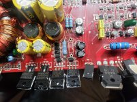
Okay, I attached a pic of the preamp board, after I realized what must likely is the shorted component. Remove C424 and C224 one at a time you will find a shorted 10uf/25v capacitor.
You will find four black rectangles with a white band denoting the positive terminal next to the U201,U40-NJM2068 opamps.
After replacing with a new cap what do you read in ohms across it?
So without the preamp board installed do you have all of your rail voltages?
Okay, I attached a pic of the preamp board, after I realized what must likely is the shorted component. Remove C424 and C224 one at a time you will find a shorted 10uf/25v capacitor.
You will find four black rectangles with a white band denoting the positive terminal next to the U201,U40-NJM2068 opamps.
I removed c524 because on the board it was a direct short but when I took the cap off and tested it it read 47ohms. I replaced it anyway and still have a short on c524 along with c691 right next to it. I also replaced c691
Attachments
You sir, are a genius! Thank you for taking the time to help me. I couldnt have done it without you.
Glad too help! I'm not a genius, but after 30 plus years in electronics and 20 years working on Kicker amps, I might have picked up a clue or two!
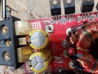
Measure the Vdc for the preamp header pins shown in attachment. Use -spkr ground for the black probe and post results.
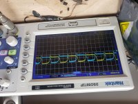
If Possible post screen shots of waveforms for FR.RR,FL,RL,SUB
FR_IN
RR_IN
-15V
REMOTE
+BATT
-15V
GNDA
SUB_IN
FL_IN
RL_IN
RL_IN
+15V
GNDA
GNDP
+15V
REMBAS
SUB_PRE
If Possible post screen shots of waveforms for FR.RR,FL,RL,SUB
FR_IN
RR_IN
-15V
REMOTE
+BATT
-15V
GNDA
SUB_IN
FL_IN
RL_IN
RL_IN
+15V
GNDA
GNDP
+15V
REMBAS
SUB_PRE
Attachments
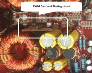
I suspect this is a muting problem.
Measure the Vdc at Q27-C3875GR. Black probe on on speaker ground. You should have approximately a -20Vdc at the collector of Q27.
The Muting circuit consists of Q24-C3875GR, Q25-MMBF170, Q26-A1504GR, D16-20V zener and of course Q27.
Measure the Vdc at Q27-C3875GR. Black probe on on speaker ground. You should have approximately a -20Vdc at the collector of Q27.
The Muting circuit consists of Q24-C3875GR, Q25-MMBF170, Q26-A1504GR, D16-20V zener and of course Q27.
Nevermind. The protection was on because I had my power supply set to 10v. As soon as I turned it up the protection light went off. Thanks again for all ur help
- Home
- General Interest
- Car Audio
- Kicker zx900.5