My audio addiction has advanced to the point I am interested in designing my own equipment. I have been lurking here for some time and thought I’d share the results from my first project.
I bought the “Vintage 6SL7 Phono Stage” circuit board from Tavish Design. They provide the board, schematics, parts list, and instructions. They also sell completed units.
This was my first DIY project.
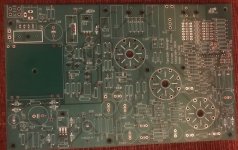
Sourcing the parts from DigiKey and Mouser and building the board was straightforward enough. Everything went together easily and the instructions were comprehensive and easy to follow.
I wanted to design a chassis that compliments the rest of my system as well as the turntable that I plan to buy soon.
I settled on using the freely available Protocase designer software available from the Protocase fabrication company in Canada.
This CAD program comes supplied with basic templates for various types of enclosures, including five-sided enclosures, U-shaped enclosures, L-shaped enclosures, among others. The program provides a library of sheet metal stock (cold rolled steel, stainless steel, and aluminum), and all of the various fasteners that they offer (studs, standoffs, nuts, etc.) The program is also aware of all the powder coat finishing options that the offer, which can be previewed on their web site. The CAD program can also be used to create cutouts in sheet metal parts of any size or shape. The CAD program can also be used to add graphics to any surface. They offer silk screening and digital inkjet printing.
Protocase uses an automated CAD/CAM process, where sheet metal is laser cut, folded, welded, and finished.
The phono preamp board is intended to be mounted in a chassis on top of standoffs, with cutouts that mate with board-mounted connectors.
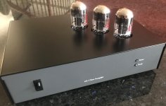
I chose to design a U-shaped enclosure with a cover that is fastened with screws to the sides of the chassis and lifts off from the top. I chose this design because the board contains DIP switches for setting resistive and capacitive loading of moving magnet and moving coil cartridges, so occasional access to the board could be necessary.
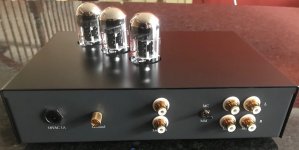
This was my first experience at designing a chassis and using CAD software and I didn’t have any dimensions available for the board or the connectors. Not being brave enough to chance a misalignment of connectors, I decided to mount the board on standoffs in the center of the chassis. I used thru-hole power, ground, and BNC connectors and wired these connectors to the board directly. I also used a snap-fit power switch and press-fit LEDs for the indicators.
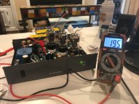
I bought a digital caliper and took careful measurements of all hole positions on the board before assembly.
The CAD program places cutouts and fasteners using X/Y offset measurements from an origin, so I first had to calculate the offsets for all of the cutouts. I chose to lay out the chassis first in Visio. This allowed me to accurately position all of the cutouts. I then used Visio’s dimension features to calculate offsets relative to the origin. I chose to use the digital inkjet option for the labeling because this was considerably less expensive than silk screening. I was very happy with the finished results.
I was relieved when the chassis arrived a few days after placing the order and holes in the board aligned with the standoffs and the connectors fit.
I did make two mistakes. I neglected to account for the thickness of the power coat finish when specifying dimensions for the cutouts. I had to slightly enlarge the diameter of two holes on the back panel, but the mistake is not visible.
Pictures of the circuit board and finished chassis are attached.
I bought the “Vintage 6SL7 Phono Stage” circuit board from Tavish Design. They provide the board, schematics, parts list, and instructions. They also sell completed units.
This was my first DIY project.
Sourcing the parts from DigiKey and Mouser and building the board was straightforward enough. Everything went together easily and the instructions were comprehensive and easy to follow.
I wanted to design a chassis that compliments the rest of my system as well as the turntable that I plan to buy soon.
I settled on using the freely available Protocase designer software available from the Protocase fabrication company in Canada.
This CAD program comes supplied with basic templates for various types of enclosures, including five-sided enclosures, U-shaped enclosures, L-shaped enclosures, among others. The program provides a library of sheet metal stock (cold rolled steel, stainless steel, and aluminum), and all of the various fasteners that they offer (studs, standoffs, nuts, etc.) The program is also aware of all the powder coat finishing options that the offer, which can be previewed on their web site. The CAD program can also be used to create cutouts in sheet metal parts of any size or shape. The CAD program can also be used to add graphics to any surface. They offer silk screening and digital inkjet printing.
Protocase uses an automated CAD/CAM process, where sheet metal is laser cut, folded, welded, and finished.
The phono preamp board is intended to be mounted in a chassis on top of standoffs, with cutouts that mate with board-mounted connectors.
I chose to design a U-shaped enclosure with a cover that is fastened with screws to the sides of the chassis and lifts off from the top. I chose this design because the board contains DIP switches for setting resistive and capacitive loading of moving magnet and moving coil cartridges, so occasional access to the board could be necessary.
This was my first experience at designing a chassis and using CAD software and I didn’t have any dimensions available for the board or the connectors. Not being brave enough to chance a misalignment of connectors, I decided to mount the board on standoffs in the center of the chassis. I used thru-hole power, ground, and BNC connectors and wired these connectors to the board directly. I also used a snap-fit power switch and press-fit LEDs for the indicators.
I bought a digital caliper and took careful measurements of all hole positions on the board before assembly.
The CAD program places cutouts and fasteners using X/Y offset measurements from an origin, so I first had to calculate the offsets for all of the cutouts. I chose to lay out the chassis first in Visio. This allowed me to accurately position all of the cutouts. I then used Visio’s dimension features to calculate offsets relative to the origin. I chose to use the digital inkjet option for the labeling because this was considerably less expensive than silk screening. I was very happy with the finished results.
I was relieved when the chassis arrived a few days after placing the order and holes in the board aligned with the standoffs and the connectors fit.
I did make two mistakes. I neglected to account for the thickness of the power coat finish when specifying dimensions for the cutouts. I had to slightly enlarge the diameter of two holes on the back panel, but the mistake is not visible.
Pictures of the circuit board and finished chassis are attached.
Attachments

Hi - I just finished building this over the holidays as well. My first DIY project of this magnitude. I am SO impressed with the sound quality!
I'm also searching for a case but have zero experience with CAD, etc. Is it possible to share your files as a starting point / reference?
I'm also searching for a case but have zero experience with CAD, etc. Is it possible to share your files as a starting point / reference?