One 594 is for the rail supply. The other is for driver voltages.
What's the DC voltage on the 594 for the rails? Copy and paste and fill in the following:
Pin 1:
Pin 2:
Pin 3:
Pin 4:
Pin 5:
Pin 6:
Pin 7:
Pin 8:
Pin 9:
Pin 10:
Pin 11:
Pin 12:
Pin 13:
Pin 14:
Pin 15:
Pin 16:
What's the DC voltage on the 594 for the rails? Copy and paste and fill in the following:
Pin 1:
Pin 2:
Pin 3:
Pin 4:
Pin 5:
Pin 6:
Pin 7:
Pin 8:
Pin 9:
Pin 10:
Pin 11:
Pin 12:
Pin 13:
Pin 14:
Pin 15:
Pin 16:
U2 is for the rails.
Follow pin 12 of U2 back to the collector of a PNP transistor. It may be the transistor near R4.
As soon as real help shows up, I'll stop posting. He will have the proper diagrams.
Follow pin 12 of U2 back to the collector of a PNP transistor. It may be the transistor near R4.
As soon as real help shows up, I'll stop posting. He will have the proper diagrams.
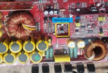
It's very common for the 2SB649 to become weak. Replace if needed. Are you getting any DC voltage on any of the pins? Measure from the Battery terminal Ground. Also check the DC voltages on Q2- KTC4401 and ZD1-1N5231B.
Ok here's the voltages on U2
Pin 1: 1.111v
Pin 2: 3.5v
Pin 3: 0v
Pin 4: 204mv
Pin 5: 1.49v sawtooth wave
Pin 6 3.46v:
Pin 7 5.9mv:
Pin 8: 5.9mv
Pin 9: 5.9mv
Pin 10: 5.9mv
Pin 11 5.7mv:
Pin 12: 0v
Pin 13: 5.02v
Pin 14 5.02v:
Pin 15: 5.02v
Pin 16: 3.49v
Pin 1: 1.111v
Pin 2: 3.5v
Pin 3: 0v
Pin 4: 204mv
Pin 5: 1.49v sawtooth wave
Pin 6 3.46v:
Pin 7 5.9mv:
Pin 8: 5.9mv
Pin 9: 5.9mv
Pin 10: 5.9mv
Pin 11 5.7mv:
Pin 12: 0v
Pin 13: 5.02v
Pin 14 5.02v:
Pin 15: 5.02v
Pin 16: 3.49v
I meant to say Q1-KTC4401. List the DC voltages around Q1,Q2 and ZD1. Without B+ on Pin 12 of U2 you will not have drive from U2 Pins 9 & 10. If you can, replace Q2-2SB649.
Correction I meant D1-1N5231B It's on the remote line.
Perry is right Pins 13,14,15 would not have 5 volts without B+ on Pin 12. Recheck DC voltages on Q1,Q2 and D1 and then look at the voltage on U2 Pin 12. It's possible the collector(middle pin)of Q2 is low. High enough to power U2 and generate sawtooth and 5v regulator voltages, but too low to power the drive pins. Pins 8 and Pins 11 are the pull ups for Pins 9 and 10 and should have ~12 volts.
Perry is right Pins 13,14,15 would not have 5 volts without B+ on Pin 12. Recheck DC voltages on Q1,Q2 and D1 and then look at the voltage on U2 Pin 12. It's possible the collector(middle pin)of Q2 is low. High enough to power U2 and generate sawtooth and 5v regulator voltages, but too low to power the drive pins. Pins 8 and Pins 11 are the pull ups for Pins 9 and 10 and should have ~12 volts.
Ok here's the voltages on U2
Pin 1: 1.111v
Pin 2: 3.5v
Pin 3: 0v
Pin 4: 204mv
Pin 5: 1.49v sawtooth wave
Pin 6 3.46v:
Pin 7 5.9mv:
Pin 8: 5.9mv
Pin 9: 5.9mv
Pin 10: 5.9mv
Pin 11 5.7mv:
Pin 12: 0v
Pin 13: 5.02v
Pin 14 5.02v:
Pin 15: 5.02v
Pin 16: 3.49v
Removing d7 did nothing. I replaced Q1 and now the voltages on u2 are as follows
Pin 1: 1.111v
Pin 2: 3.5v
Pin 3: 4.79
Pin 4: 2mv
Pin 5: 1.49v sawtooth wave
Pin 6 7.3v:
Pin 7 0
Pin 8: 7.2v
Pin 9: 6.05v
Pin 10: 6.05v
Pin 11 6.5v:
Pin 12: 10.5v
Pin 13: 0v
Pin 14 9v
Pin 15: 0
Pin 16: 5.5v
Pin 1: 1.111v
Pin 2: 3.5v
Pin 3: 4.79
Pin 4: 2mv
Pin 5: 1.49v sawtooth wave
Pin 6 7.3v:
Pin 7 0
Pin 8: 7.2v
Pin 9: 6.05v
Pin 10: 6.05v
Pin 11 6.5v:
Pin 12: 10.5v
Pin 13: 0v
Pin 14 9v
Pin 15: 0
Pin 16: 5.5v
You may have a softstart issue. The voltages on Pins 8 and 10 seem low. Do you have stable rail voltages?
U2-TL594 PWM chip appears to be working and you have drive from Pins 9 & 10.
I haven't worked on one of these amps for sometime now, and don't recall if the IRF3205's need to be in place for the amp to come out of protection and power up.
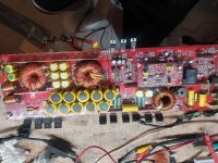
The power supply has four banks of three IRF3205 mosfets. Replace one in each bank. Q31,Q32,Q37 and Q38 will do.
Just one note, I noticed that Q13 is stuffed underneath the Class D driver card. The metal backing may be shorting to something underneath the card. This may not be the case but I recommend that you reposition Q13.
I haven't worked on one of these amps for sometime now, and don't recall if the IRF3205's need to be in place for the amp to come out of protection and power up.
The power supply has four banks of three IRF3205 mosfets. Replace one in each bank. Q31,Q32,Q37 and Q38 will do.
Just one note, I noticed that Q13 is stuffed underneath the Class D driver card. The metal backing may be shorting to something underneath the card. This may not be the case but I recommend that you reposition Q13.
ok so I had the amp functional with one fet per bank in the output section. I put them all in unaware that one of the gate resistors was out of tolerance. When I applied power the amp made a strange sound and now when i power it up I have drive on the input of the ps fets but the 12v that's supposed to be on the middle pin isn't there after I fit the fets. If I remove them it comes back.
- Home
- General Interest
- Car Audio
- Kicker zx1500.1