So a blast from the past here.. I had to use the wayback machine to get the schematic and writeup:
The Dayton II Project
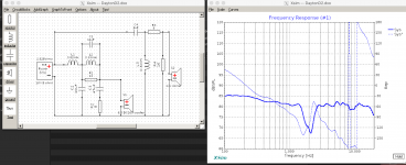
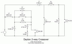
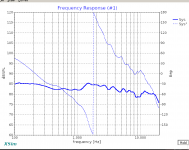
The writeup specifically calls out using a 2nd order high pass and tweeter with positive polarity, vs testing with a 3rd order and inverted polarity. The thing is, when I model it, nothing seems quite 'right' which might be from drivers and spec data files changing with time? You can see in the attached images the original crossover, my Xsim version of it, and the poor results from the sim. Inverting the tweeter does improve things, but is also not great. (also pictured)
I can obviously tweak this to get different results, but the drivers I have ARE from many years ago and possibly different and better matching the measured results at the wayback link? Or did I make a mistake anyone can spot with the schematic in Xsim ?
The Dayton II Project
The writeup specifically calls out using a 2nd order high pass and tweeter with positive polarity, vs testing with a 3rd order and inverted polarity. The thing is, when I model it, nothing seems quite 'right' which might be from drivers and spec data files changing with time? You can see in the attached images the original crossover, my Xsim version of it, and the poor results from the sim. Inverting the tweeter does improve things, but is also not great. (also pictured)
I can obviously tweak this to get different results, but the drivers I have ARE from many years ago and possibly different and better matching the measured results at the wayback link? Or did I make a mistake anyone can spot with the schematic in Xsim ?
Attachments
Uncertain, but there are some things to note, for example there may be a little physical offset that has gone unaccounted for.
It seems unlikely that a second or third order tweeter filter be as readily interchangeable. I'm noting the need to reverse polarity so there must have been enough of a change. Also that there be difficulty fitting one in with the woofer. Maybe this design wasn't simmed?
Then there's mention of bias due to concerns about connecting the tweeter with reverse polarity, suggesting compromises perhaps?
I do not know if it was simmed or not 20ish years ago, but it was certainly measured, and his measurements look better than my sims. What do you mean about physical offset? Is there a way to set driver spacing in Xsim that I have missed?
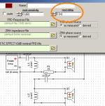
Well don't I feel dumb! Thanks a bunch! I am not sure which way to adjust it, still reading conflicting info, but adding 1.5" delay to the tweeter sure does smooth it out. The thing is, I think the delay needs to go on the DC160-8 6.5" woofer, not the tweeter. Adding the delay to the woofer does improve things, but not nearly as much as on the tweeter.
Ok - so Wayne J is likely ? to have measured the actual in box responses. These will alter frequency response of drivers in box (baffle step and diffraction) and therefore phase.... Phase changes affect crossovers.
I am also assuming the phase information within the parts express files is good, but this will change with an inbox measurement.
If you want to get as close as possible - you need to subtract the measurement conditions in the parts express data (IEC baffle is a default) then add in wayne j's box baffle step and diffraction response. then extract minimum phase (do this for each driver). Your Z offset will be required still (as you've found above) since you are not using relative phase (which in a measurement takes the voice coil offset into account), but derived minimum phase (from the FR response).
As presented by a manufacturer I'd expect minimum phase content, being measured on an infinite baffle. This means it should be easy enough to verify. Adding a box however, I wouldn't expect to 'extract' anything without a time based measurement.Dave Bullet said:I am also assuming the phase information within the parts express files is good,
It shouldn't matter which, delay on one or negative delay on the other.. except that sometimes it can be more difficult to perceive the result when the same information is displayed differently.I think the delay needs to go on the DC160-8 6.5" woofer, not the tweeter. Adding the delay to the woofer does improve things, but not nearly as much as on the tweeter.
- Home
- Loudspeakers
- Multi-Way
- Wayne J Dayton 2's crossover in Xsim