Hi guys, I'm Brad, first post here, been lurking and learning for a while now.
I wanted to share my build of the Forewatt preamp. This one came from the scrap box, and is my first scratch amp build, tube or otherwise. Prior to this I've just repaired equipment, or followed kits to modify it.
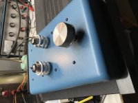
The preamp is built in two chassis, one for the audio circuitry, and the other for the power supply. Here's the preamp.
I did check all the old caps before deciding to use them...
I wanted to share my build of the Forewatt preamp. This one came from the scrap box, and is my first scratch amp build, tube or otherwise. Prior to this I've just repaired equipment, or followed kits to modify it.
The preamp is built in two chassis, one for the audio circuitry, and the other for the power supply. Here's the preamp.
I did check all the old caps before deciding to use them...
Attachments

Rectifiers
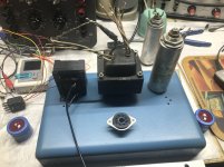
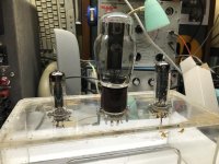
I decided to build a tube power supply for the preamp. However, it did not seem like a good idea to just have the rectifiers laying down on the bench. I needed something to hold them as I worked out the supply. This is what I came up with. It has an octal socket, a 9 pin, and a 7 pin.
for reference, the rectifiers in it are a 5R4GY, a 6CA4, and a 6X4. At the low current level of the preamp, just about anything will do.
Attachments
These old oil capacitors are quite good. I have some of them at home, but still unused by me. In any case, consider the possibility of DC and Ac leakage to ground, from the internal cap through the metal box containing the unit.
Anyway, congratulations for your first own project. Mine was a 80mts AM transmitter far in 1985 aprox.
Anyway, congratulations for your first own project. Mine was a 80mts AM transmitter far in 1985 aprox.
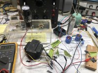
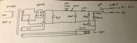
The Power Supply
I started out by using PSUDII to craft a tube power supply. I found a Victory VPT-3 transformer, and with some google fu came up with the specs on it!
I did measure it, but that didn't tell me what amp capacity the heater windings had. Turns out that the trans has a 2.0 amp rating on both the 5V and 6.3V heater windings. Armed with this info, I found that of the 5 volt rectifiers I had, only the big 5R4GY had that low of a heater current. I could have used tubes with 6.3 volt heaters though. Anyway, this is what I eventually came up with. I did run that Ancient Cornell-Dubilier 4uF 600V cap through some tests as I didn't think that a cap from the 1940's would work! It actually measures better than many much newer ones - for how long I don't know, but maybe I'll find out.
The probable part layout is shown here.
The supply is running at 218 VDC, with 2.6 mV of ripple now. I may add some small film caps - 0.047 uF - to the last dropping resistors after the main leg splits into dual rails.
The heaters are still AC, but so far hum is not an issue. I think the 6.3 volt supply would have enough capacity to handle being converted to DC if that should be needed.
This is my first ever scratch built tube supply, so comments are appreciated.