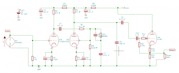
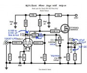
I'm planning on building the preamp stage from the 1968 edition of the RCA Tube Receiving manual. This circuit appears in many places, even a number of places on this forum:
https://www.diyaudio.com/forums/tubes-valves/213241-help-rca-tube-manual-riaa-phono-stage-3.html
https://www.diyaudio.com/forums/tubes-valves/301088-rca-receiving-tube-manual.html
https://www.diyaudio.com/forums/tubes-valves/156541-own-riaa-tube-preamp.html
https://www.diyaudio.com/forums/tubes-valves/129119-tube-preamp-riaa.html
I've attached the projects BOM (I'm starting completely from scratch, don't have parts hanging around). It comes out to ~$240. I want to use a tube power supply. I'm using the power supply from the RCA manual. It uses a 6X4 tube with a 300-0-300 transformer. The filter I've selected is a pair of capacitors (47 uF) and two 500 ohm resistors. Under a 60 mA load, this should put out the 250 volts I need for B+. How do I estimate the current load for the circuit? It seems under lower load, the output voltage of the power supply will be higher.
I've also added a cathode follower to boost the output from 0.55 volts to (hopefully) something closer to line level (copy-pasted from here: The Valve Wizard -Cathode Follower). I'm using this as input to a preamp that expects a ceramic cartridge output. These carts are 1.5 V RMS if I remember right.
Design goals:
- All tube design, power supply and signal path
- Passive RIAA equalization
- Standalone component from the rest of the system (ie I don't want to reuse power supply voltage from the power amplifier)
- Close RIAA compliance (within 1 dB). I know there are designs that get closer. I want to be as close as possible, but I also want a simple circuit for my first tube project.
- 60's design, this is going in a console from the late 60s, and I like the idea of a contemporary design.
Questions:
- Can I simulate this circuit in KiCAD? I can't for the life of me get reasonable outputs
- Can I save a bit and use 22uF capacitors in place of the 20 uF and the 25 uF capacitors that are not in the RIAA equalization path?
- Have I made any mistakes in the components I've picked out?
- Do I need to tweak any of the values in the cathode follower?
- The cathode follower calls for a 280V B+, I'll be using 250 V, is that OK?
Circuit schematic and BOM attached.
Attachments
The caps in the power supply decoupling are non-critical. 22uf will be fine - use what you can get cheapest.
The cathode follower will NOT provide a higher voltage. It will provide better current drive to the next stage and mean you will not have problems driving lower impedance loads. You could replace the valve with a mosfet for the same effect and at reduced power supply requirements.
If you go ahead with the valve cathode follower, the B+ voltage is non-critical within reason. 250v will be fine.
Last edited:
The cathode follower will prevent the second stage from being loaded down, so in effect
it will provide voltage gain when using it. But it's the signal at the second plate that will increase.
The cathode follower's output will still be less than its input.
it will provide voltage gain when using it. But it's the signal at the second plate that will increase.
The cathode follower's output will still be less than its input.
Last edited:
To squeeze more net gain out of the setup, replace R5 with a quality constant current source (CCS) configured in the 900 μA. to 1 mA. range.
I too buffer the RCA setup, but use a DC coupled MOSFET in the voltage follower role. No heater power needed and there are no heater to cathode potential worries. Grid leak biasing the 2nd gain block is a Thorsten Lösch suggestion that can help bass extension. The rationale is lightly loading the EQ network.
24 Kohms, instead of RCA's 22 Kohms, in the RIAA EQ network is more accurate. Remember, post WW2 the huge assortment of high precision metal film resistors we take for granted was not available. RCA specified the readily available 22 Kohms, for quite valid practical reasons.
Attachments

The cathode follower will prevent the second stage from being loaded down, so in effect
it will provide voltage gain when using it. But it's the signal at the second plate that will increase.
The cathode follower's output will still be less than its input.
Can you help me understand output impedance? The schematic says the output impedance should be 220k Ohms. I have no clue what the impedance of my preamp is. Do I just connect an ohmmeter across the input jacks on the preamp?
My goal was to have the output of the circuit "at line level" which doesn't seem to be what is the case for the circuit directly out of the tube manual.
I really want to keep this all tube. Its philosophically driven by the fully analog nature of the tube. I know its eccentric, but a lot of this hobby is eccentric, and I love the idea of understanding the analog waves from the grooves of the record all the way to my ears.To squeeze more net gain out of the setup, replace R5 with a quality constant current source (CCS) configured in the 900 μA. to 1 mA. range.
I too buffer the RCA setup, but use a DC coupled MOSFET in the voltage follower role. No heater power needed and there are no heater to cathode potential worries. Grid leak biasing the 2nd gain block is a Thorsten Lösch suggestion that can help bass extension. The rationale is lightly loading the EQ network.
24 Kohms, instead of RCA's 22 Kohms, in the RIAA EQ network is more accurate. Remember, post WW2 the huge assortment of high precision metal film resistors we take for granted was not available. RCA specified the readily available 22 Kohms, for quite valid practical reasons.
I'll bump the RIAA resistor to 24k. I was really hoping to get this working in KiCAD so I could tune the values a bit, but it doesn't look like that's a simple proposition.
FWIW, the FET is 100% analog too. Any voltage follower presents a high impedance to the preceding circuitry. You easily satisfy RCA's 220 Kohm specification. The O/P impedance of a 12AU7/ECC82 section cathode follower will be approx. 350 Ω, given a gm just shy of 3 mA./V.
BTW, the "best" HF performance may be obtained by reducing C8 in value or (perhaps) completely eliminating it. RCA was talking about wiring effects there.
BTW, the "best" HF performance may be obtained by reducing C8 in value or (perhaps) completely eliminating it. RCA was talking about wiring effects there.
Can you help me understand output impedance? The schematic says the
output impedance should be 220k Ohms.
My goal was to have the output of the circuit "at line level" which doesn't seem
to be what is the case for the circuit directly out of the tube manual.
The cathode follower has a low output impedance, and is uncritical of external loading.
The value mentioned was for the external load impedance, not the output impedance.
Output impedance is the effective (by circuit behavior) series resistor in the output stage of a circuit.
Output impedance - Wikipedia
The 220k loading spec (without cathode follower) was so the circuit operation would not
be degraded ( loss of gain, higher distortion, and loss of bass) by using a lower load impedance.
This preamp's output is indeed at line level, which is a volt or so.
Line level - Wikipedia
Last edited:
You should skip C10.
Why did you choose to use the triode section of ECL82's as the cathode follower? Are you going to use the pentode sections of the ECL82's for something else?
Looking at the Ia/Va curves of the triode section in the datasheet for the ECL82, i think R13 (470) en R14 (18K) should be higher in value (something like 1K and 68K). On the site of the Valve Wizard there is an explanation of how to calculate those values: The Valve Wizard -Cathode Follower
To summarize the changes:
Drop C10, drop C8, and 24k in the RIAA equalization, do the correct calculations for the resistors in the cathode follower.
The plan was to use one tube for both channels, I thought (maybe incorrectly) that I could use the triode section for the right channel and the pentode for the left?
I added the cathode follower because the output impedance was so high. Without the cathode follower, can I plug this into a preamp that expects a ceramic cart on the phono input? If so, I would just build the vanilla RIAA circuit with the 24k RIAA resistor, and a 6x4 tube power supply.
Drop C10, drop C8, and 24k in the RIAA equalization, do the correct calculations for the resistors in the cathode follower.
You should skip C10.
Why did you choose to use the triode section of ECL82's as the cathode follower? Are you going to use the pentode sections of the ECL82's for something else?
Looking at the Ia/Va curves of the triode section in the datasheet for the ECL82, i think R13 (470) en R14 (18K) should be higher in value (something like 1K and 68K). On the site of the Valve Wizard there is an explanation of how to calculate those values: The Valve Wizard -Cathode Follower
The plan was to use one tube for both channels, I thought (maybe incorrectly) that I could use the triode section for the right channel and the pentode for the left?
I added the cathode follower because the output impedance was so high. Without the cathode follower, can I plug this into a preamp that expects a ceramic cart on the phono input? If so, I would just build the vanilla RIAA circuit with the 24k RIAA resistor, and a 6x4 tube power supply.
The buffering voltage follower is a good idea, if only because of interconnect cabling capacitance. The 'X7 triode is a wimp that "can't fight its way out of a wet paper bag".
If the original RCA circuit is implemented on the same chassis as circuitry used with piezoelectric cartridges, buffering is not needed, unless some sort of recording device is to be driven too. It's all about the inability of the 'X7 triode to drive anything resembling a significant load.
If the original RCA circuit is implemented on the same chassis as circuitry used with piezoelectric cartridges, buffering is not needed, unless some sort of recording device is to be driven too. It's all about the inability of the 'X7 triode to drive anything resembling a significant load.
The plan was to use one tube for both channels, I thought (maybe incorrectly) that I could use the triode section for the right channel and the pentode for the left?
Why not use a twin triode like 5965, 12AV7, 12AT7 or 12AU7 for the cathode followers instead of a triode-pentode? That way you can make two identical channels for stereo. None of the twin triodes above are expensive.
The plan was to use one tube for both channels, I thought (maybe incorrectly) that I could use the triode section for the right channel and the pentode for the left?
Even though a cathode-follower has near to unity gain, the two channels would not be the same on other parameters. On top of that: The pentodes section of the ECL82 (connected in triode mode) would need way more current (some 20 mA) to operate than the triode section (around 1 mA).
Like Rongon said: Use a twin triode with two equal triodes. Make sure the maximum cathode to heater voltage of that twin triode is high enough for the cathode voltage (100 V will do so the 12AU7 would be a good choise).
> The cathode follower has a low output impedance, and is uncritical of external loading.
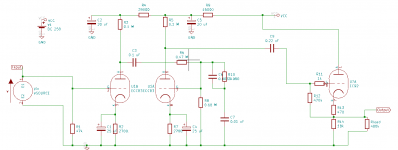
Yes; but that CF will NOT properly drive the 600 ohms shown on his plan. SPICE will show big clipping at a volt or two of signal, and 5% THD before that. I can't imagine he really has to drive 600 ohms. He may face 20k, which the CF will do a
whole lot better than the naked 2-triode amp.
Missing a cap here also.
Attachments
Last edited:
Good catch!
What is the 600 ohm load that needs to be driven? Modern day amps and preamps are supposed to have a 10k ohm input impedance, correct? I've modeled 12AT7 and 12AU7 cathode followers into a 10k load, and they'll suffice.
Better yet would be a 5687 or 6N6P, since those have lower plate resistance, so can drive 10k with relative ease. The downside is the need for higher current capacity from the power supply.
Eli's MOSFET source follower on the output is looking better and better.
The original RCA naked two-triode phono preamp was meant for connection to a vacuum tube control amp with high input impedance of 220k minimum. That's not suitable for most contemporary products.
--
Last edited:
This is the tube first project that I've done from scratch with modifications to the original schematic. I was trying to get the circuit to simulate in KiCAD. A lot of the things that are being pointed out are the result of my ignorance.
I put 680 ohms as the load because that's what the output impedance of the cathode follower was. If its still 22k Ohms, I will update the circuit. It was mostly to try to get KiCAD to run the simulation.
As far as the ECL82 vs true twin triode tubes, ECL82 was the closest I could find in the valve section of KiCAD library. I have the 12AU7 in the BOM for the project.
This will be plugged into a Voice of Music Model 866 console which had a preamp with three input sources and a 15 watt per channel power amplifier. Its from the mid 60s, which is why I wanted a contemporary design vice something modern.
I put 680 ohms as the load because that's what the output impedance of the cathode follower was.
For simulation purposes, I like to put something like 470k as the no-connection load resistor on the output of the circuit, and then add a 'phantom' resistor 'Rload' going from the output to ground, to simulate the expected load.
That way you can make Rload = 10k if you expect the circuit to drive a solid-state power amp with a 10k ohm volume control (pretty standard these days) or you can make Rload = 47k in accord with how things were back in the 1970s and '80s.
This will be plugged into a Voice of Music Model 866 console
That probably has a Phono input already, with its own phono preamp. Please forgive me if you already know this, but you will want to connect the output from this proposed preamp to one of the line level inputs on the console (if it has those). In the 1960s it was usual for the line inputs to have >47k input impedance, so you should be fine with a 12AU7 cathode follower.
ECL82 vs true twin triode tubes, ECL82 was the closest I could find in the valve section of KiCAD library
The triode section of the ECL82 is more like a 6SL7 (similar to 12AX7 but not identical) than a 12AU7. Does your KiCAD library have 6C4 or 6AN8A? 6C4 is a 7 pin single triode version of 12AU7, and 6AN8A has a triode section similar to a 12AU7. If there's a 6SN7 or 6J5 model, you could use that too. Those are triodes that are fairly similar to 12AU7.
I hope that helps a little.
--
Last edited:
OK, KiCAD doesn't have a 6C4 or 6AN8A. It does have a single triode EC92 which I've updated. I haven't changed the resistors because I will use a 12AU7 in the real circuit, and the values are the same as the CF on TubeWizard.
For the power supply, I've chosen a filter that will give the following voltages under various loads (no choke, two 500 ohm resistors and two 40 uF capacitors):
Voltage, Load
345V, 20 mA
230V, 40 mA
250V, 60 mA
Should I use a filter assuming a 20 mA current? In that case I would just a different filter:
250V, 20 mA
230V, 40 mA
220V, 60 mA
This filter has a choke of 12H and a 40 uF capacitor, no resistors.
Attachments
- Home
- Amplifiers
- Tubes / Valves
- RIAA RCA tube preamp (1968 tube receiving manual)