Hi guys, I have some questions about my Zeus Gen X rev. B. The amplifier plays fine, but I think that rail voltage is a bit low. In the past I had a similar Zeus, but it was a rev.A and the rail voltage was +/-58 V. My actual rev. B, instead, measures +/- 49.2 V, no matter the input voltage from 9.5V to 13.7V (so, regulation works).
I made a quick measurement without load: since the distortion at the output start to rise exactly at 34 Vrms without load (theoretically 289W/4ohm @ 0.01 % THD), I thinked that the rated output power cannot be reached (325W/4ohm @ 0.01% THD), ending that the rail voltages are too low to produce full power.
With 13.74V input, these are the TL494 readings:
1: 1.86V
2: 1.86V
3: 3.08V
4: 0.426V
5: 1.413V
6: 3.37V
7: 0.0024V
8: 13.74V
9: 0.914V
10: 0.830V
11: 13.74V
12: 13.74V
13: 4.87V
14: 4.87V
15: 4.87V
16: 0.027V
Attachments:
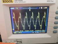
PSU fet, gate and drain waveforms with 13.74V input
I made a quick measurement without load: since the distortion at the output start to rise exactly at 34 Vrms without load (theoretically 289W/4ohm @ 0.01 % THD), I thinked that the rated output power cannot be reached (325W/4ohm @ 0.01% THD), ending that the rail voltages are too low to produce full power.
With 13.74V input, these are the TL494 readings:
1: 1.86V
2: 1.86V
3: 3.08V
4: 0.426V
5: 1.413V
6: 3.37V
7: 0.0024V
8: 13.74V
9: 0.914V
10: 0.830V
11: 13.74V
12: 13.74V
13: 4.87V
14: 4.87V
15: 4.87V
16: 0.027V
Attachments:
PSU fet, gate and drain waveforms with 13.74V input
Attachments
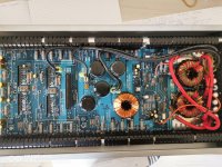

Those amps had a potentiometer to adjust the top rail to 56v and had markings for the other two rail voltages. They also had multiple transformer taps, rectifiers and switches for those voltages. I see none of that here. If they abandoned the vari-power system, they would have had to lower the rail voltage to prevent overheating unless they used a heatsink with much more surface area.
The strange thing is that at power up the voltage reaches +/-58V and after half a second it slowly drop to +/- 49.2 V. I don't know if it can be considered "normal" operation, I doubt it.
I tried myself to understand what affects the regulation and I found Q7 shorted from B to C, B to E open. It's a TIP 41C named "FAN " on the pcb. I replaced it with a BUV27 because it's the only NPN that I have on hand. Now rail voltage is +/- 57 V, so I assume this is the correct operation.
I don't know why Q7 has failed, but surely I had never put a sensible node externally accessible to the user.
I'll post a rough schematic so this sentence will be clearer.
Thank you Perry 🙂
I don't know why Q7 has failed, but surely I had never put a sensible node externally accessible to the user.
I'll post a rough schematic so this sentence will be clearer.
Thank you Perry 🙂
If you mean the circuit that regulates the rail voltage, yes, it works. Tomorrow I'll post the schematic so we can talk about it
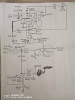
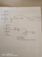
Yes, but now I have understood how the rail voltage regulation works in this amplifier and the fault has been detected. It seems that the dead time controller output goes proportionally high as the temperature goes high, turning on Q7. As Q7 turns on, its collector is tied to ground so the voltage on pin 2 of the TL494 goes up and the rail voltage goes down. If a fan is connected between +12v and FAN pin (Q7's collector), the current in the fan increases as the Q7's collector goes to ground.
So, the output power is reduced as the temperature goes high, I assume.
I'll try to contact ZED about NW1.
So, the output power is reduced as the temperature goes high, I assume.
I'll try to contact ZED about NW1.
- Home
- General Interest
- Car Audio
- Hifonics Zeus X