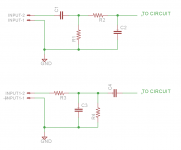
When laying out a PCB, what is the best order in which to place the input resistors and caps? Should the RF filter come before the DC blocking cap, or the other way around? It seems like a good idea to put the RF filter cap as close to the first input device (
op amp, JFET, etc) to minimise the trace length that can pick up noise.
I've attached an image showing two different orderings, there are other combinations possible. Are the identical, electrically speaking?

op amp, JFET, etc) to minimise the trace length that can pick up noise.
I've attached an image showing two different orderings, there are other combinations possible. Are the identical, electrically speaking?

The (first) RF cap should go as soon as possible, ideally on the socket, to stop RF entering the box and bouncing around.
A DC block cap ideally has a bleeder resistor (1M is fine) before it to ground to stop it holding charge from the last connection unplugged.
The series resistor and another small cap protect from transients and static (RCA plugs are perfectly designed for blowing up input devices as the centre pin makes contact first!) This cap also attenuates RF of course.
Series resistor will contribute Johnson noise, so keep its value modest.
The load resistor to ground can be last so it can be the input device's bias path.
So in summary: RF shorting cap to ground on connector, bleeder to ground, DC blocking cap, series protection resistor, another RF cap to ground, then load resistor to ground (or DC servo output?)
Your top circuit with an extra RF cap on the input would be fine too.
There's scope for more protection components like TVS diodes and rail-clamp diodes etc too.
Last edited: