Hey diy Community,
Got an Adam P11a active studio monitor which is none responsive when switched on; no "amp power" noise, nothing.
Swapped the fuse out, and plug.
Swapped over transformer and main capacitors which still didn't work.
Wondering if this is a common or known issue with p11a's?
Any ideas would be greatly appreciated!
I think we need to see a circuit diagram to be able to advise you 🙂
Why would you swap a transformer and caps without doing basic checks first?
If it uses a conventional mains transformer (so a large and heavy transformer, not a small transformer and a switching supply) then first steps are to check that mains is reaching the primary winding.
Maybe some pictures of the internals would help clarify what is in there.
As far as I am aware it is made with a Hypex FM module.
There is more information available for B&O Ice Power, and that's not enough to service them unless you know what you are looking for, same as Flying Mole FM amplifiers that I have been repairing for years after reverse engineering them.
There is more information available for B&O Ice Power, and that's not enough to service them unless you know what you are looking for, same as Flying Mole FM amplifiers that I have been repairing for years after reverse engineering them.
I think we need to see a circuit diagram to be able to advise you 🙂
Why would you swap a transformer and caps without doing basic checks first?
If it uses a conventional mains transformer (so a large and heavy transformer, not a small transformer and a switching supply) then first steps are to check that mains is reaching the primary winding.
Maybe some pictures of the internals would help clarify what is in there.
Attachments
Thanks 🙂
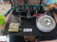
So a conventional power supply by the look of it. First checks would be to see if you have mains voltage applied to the primary windings and also that ther eis voltage across the secondaries.
You could also check the DC voltage across those large caps on the PCB as they look like reservoir caps.
Beyond that, and without a service manual showing circuit diagrams then it doesn't look good from a DIY aspect I'm afraid.