I'm having a problem with a McIntosh C26 preamp. All inputs except Phono are working beautifully. They test great on a QA401.
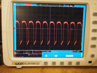
The left phono channel works fine however the right phono input channel has very substantial distortion. I believe I've narrowed the problem to the phono amp. A schematic is attached for the relevant circuit. In this section, the phono signal comes in on the coax connected to points 5 & 6. I tested the voltages according to the schematic and compared to the left channel (which works fine). They all test fine except for the voltage at the Collector of Q6. This voltage is not stable on the right channel (is stable on the left). I connected my oscilloscope to that point (i.e. collector of Q6) and get the waveform that's attached as a picture. It appears to be about 20V. Overlaid on the waveform shown in the picture is another regular (mostly sawtooth) wave of about 480kHz. The same test point on the left channel does not exhibit this waveform - just stable DC. I get this problem with any input connected or with the inputs shorted. If the input is not connected I DO NOT get the problem.
I would sure appreciate any thoughts or suggestions.
Attachments
Looks like oscillation. possibly from a bad capacitor.
Check all the resistor values in the right phono channel.
If ok, then replace the three electrolytic capacitors in that channel, C6, C8 and C16.
McIntosh C26 - Manual - Stereo Pre Amplifier - HiFi Engine
Check all the resistor values in the right phono channel.
If ok, then replace the three electrolytic capacitors in that channel, C6, C8 and C16.
McIntosh C26 - Manual - Stereo Pre Amplifier - HiFi Engine
Last edited:
Thank you. I will do that tomorrow morning.
If this does not fix it, at least they were about due for replacement anyway.
These are odd symptoms, but the capacitors are the most likely culprits.
If this works, then I'd replace those three capacitors in the left channel also.
Last edited:
Actually the 3 electrolytics are new. I will pull the resistors and verify against schematic. It's no problem to also replace the electrolytics a second time (I'm sure I have them on hand). Do I need to check the film and ceramic caps?
Well, that's different. The film/ceramic capacitors will be ok. How long after the new electrolytic capacitors
were installed did the problem start? Double-check the polarity of each.
Was any other work done on the unit?
I would not remove the resistors, since an in-circuit check is good enough to find open circuits, etc.
Don't want to damage the boards.
were installed did the problem start? Double-check the polarity of each.
Was any other work done on the unit?
I would not remove the resistors, since an in-circuit check is good enough to find open circuits, etc.
Don't want to damage the boards.
Last edited:
The problem was there right after the electrolytics were replaced, but it may also have been there prior to the replacement - it wasn't being used for phono and it works fine on all the other inputs. I did compare the resistors in-circuit to the working channel and didn't find any large variances
Ok, check the polarity of each of the three capacitors. Just compare them to the good channel.
If one is reversed, throw that one away.
Were the capacitors brand new, or from old stock in your parts cabinet?
It sounds worthwhile to try replacing them again, in case one is bad.
If one is reversed, throw that one away.
Were the capacitors brand new, or from old stock in your parts cabinet?
It sounds worthwhile to try replacing them again, in case one is bad.
The caps were all new. I never re-use, just too much risk for very little savings. And I do have them all in stock so I'll just replace.
I just verified that the polarity matches the working channel. When I replace them tomorrow, I'll verify polarity against the schematic.
I missed your earlier question. No other work was done to the unit when the electrolytics were replaced.
Problem solved - but I'm not completely sure how.
I replaced all 3 electrolytic. All tested OK on my capacitance meter but that wouldn't test leakage. I did find that C6 and C8 were 10/35 but are specified to be 10/50. I can't say that I see why it would make a difference but maybe that was the problem. I replaced with 10/50.
I checked all resistor in-circuit. I found a couple that were more than 10% out of spec. R14 and R20 are spec'd at 180K 5% and were both around 203K so I replaced them.
Now all is fine. Testing at .004%THD through the phono input at 2.5v output (rating is .1%THD)
Thanks for your help rayma - without it I'd still be scratching my head...
Last edited:
Could have been a bad solder joint, etc.
Good thought. Certainly wouldn't be the first time...
- Home
- Source & Line
- Analog Line Level
- McIntosh C26 Phono Input Problem - Please Help