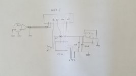
It looks like you are following the general recommendations correctly. Pin 1 of your XLR socket is meant to be connected to chassis ground, as you have shown.
The shield of your internal twisted pair could also be connected, at one end only, to the audio ground of the channel board.
The ground loop breaker you have installed between auido and chassis ground looks Ok. The 100 nF capacitor is optional, and probably won't make a difference with a well filtered linear supply. If your were using SMPS supplies, then that cap would help conduct high frequency switching noise to the chassis ground. Using the power bridge rectifier is a means of limiting the voltage across the 10 Ohm resistor. With the rectifier in place, the 10 Ohm resistor may be 1 W or even 1/2 W. If you are using a dual-mono supply, then there is an alternate way of wiring the power rectifier to support independent ground loop breakers for each channel.