I am trying to interface the balanced line out of a PA system to a camcorder that has only an unbalanced, microphone-level audio input.
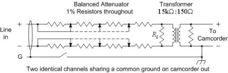
I have attached a schematic diagram of my first-cut design. It has a hum problem. I'd like your suggestions on a fix.
the PA system: Very low hum in PA applications. Output used is balanced, but not floating (it is two op-amps, each driving one of the phases, one op-amp is inverting, the other is non-inverting; on a Tascam LM-8ST).
Hum does not change as the attenuator in my interface box changes. Hum goes away completely when the camcorder is battery-powered.
Hypothesis: Camcorder DC power supply has a lot of common-mode 60 Hz component. The transformers in my interface box are from a Shure M67 microphone mixer; I guessed at the impedances. But I am driving the hi-Z side which is opposite of their intended use. Hence, the CMRR of my interface box may not be good (1% resistors are not great either).
Maybe ground the center of RL in the schematic (to camcorder ground)? Maybe add transformers on the line level inputs to improve CMRR? (I do have triad A67Js available). I wish I could put a common-mode choke on the Camcorder DC power supply . . .
Any suggestions appreciated. I suppose the easiest is to just use the battery power, but I'd like to figure out another solution if possible . . .
Tom
Attachments
Yes, that's the root cause.I am trying to interface the balanced line out of a PA system to a camcorder that has only an unbalanced, microphone-level audio input.
I have attached a schematic diagram of my first-cut design. It has a hum problem. I'd like your suggestions on a fix.
the PA system: Very low hum in PA applications. Output used is balanced, but not floating (it is two op-amps, each driving one of the phases, one op-amp is inverting, the other is non-inverting; on a Tascam LM-8ST).
Hum does not change as the attenuator in my interface box changes. Hum goes away completely when the camcorder is battery-powered.
Hypothesis: Camcorder DC power supply has a lot of common-mode 60 Hz component.
At 60Hz, the CMRR of just about any audio transformer is quite good. Which way to drive them won't matter.The transformers in my interface box are from a Shure M67 microphone mixer; I guessed at the impedances. But I am driving the hi-Z side which is opposite of their intended use. Hence, the CMRR of my interface box may not be good (1% resistors are not great either).
Definitely not.Maybe ground the center of RL in the schematic (to camcorder ground)?
You could try an A67 with a pad on the camera side.Maybe add transformers on the line level inputs to improve CMRR? (I do have triad A67Js available).
Probably wouldn't work, and would have to be huge. However, it might we worth a try to put the camera PSU on an isolation transformer, if one is available. That would float it off the power line.I wish I could put a common-mode choke on the Camcorder DC power supply .
Regarding the schematic, there's no need for a balanced attenuator on the PA side of the transformer. You can attenuate the signal with any sort of pad, the transformer is only looking at the voltage differential. Resistor match is not important either, and clearly, the hum problem isn't related to the attenuator anyway. But really, the attenuator should be on the camera side anyway, as there it would attenuate any noise along with the signal. And on the camera side, a simple L pad would be just fine. In other words, do your CMRR with the hottest signal possible, then attenuate everything equally.Any suggestions appreciated. I suppose the easiest is to just use the battery power, but I'd like to figure out another solution if possible . . .
Tom
The shield/ground should never be carried across the transformer from the camera to the PA. Transformers often have a shield connection, the good ones with an internal ground connection brought out, the cheap ones with neither. Ground should be to the unbalanced side.
You don't specifically need a step-down transformer here, a 1:1 would work so long as you pad the input to the camera.
Some transformers suffer from internal parasitics that hamper their ability to perform enough ground isolation. Some lack much of a magnetic shield, though I think the M67 transformers should be pretty good. But I suspect, in this case, just moving the attenuator to a point between the transformer and the camera will do what you need.
thanks
Thanks, Jaddie, for the information.
I will move the attenuator to be after the transformer. In that case the attenuator will decrease the signal as required, and will also decrease whatever hum is making it through the transformer.
One fear I had about the transformer (from the Shure M67) was that it might have internally connected one side of the hi-Z winding to a shield, since in the original application that particular lead was always grounded. This asymmetry would degrade the CMRR in the way I was using it. But a simple ohmmeter check showed no DC continuity from any lead to the case.
Maybe I'll just use the A67 transformers since they clearly have a shield lead and the attenuator can be built with greater loss.
Thanks again!
First, no, grounding the case to either circuit doesn't degrade CMRR, and doesn't cause "asymmetry". Second, the case would have been grounded to circuit/chassis ground of the M67, which would be correct in that application. Also note that transformer has an internal inter-winding shield, which is grounded to the case. You want that.Thanks, Jaddie, for the information.
I will move the attenuator to be after the transformer. In that case the attenuator will decrease the signal as required, and will also decrease whatever hum is making it through the transformer.
One fear I had about the transformer (from the Shure M67) was that it might have internally connected one side of the hi-Z winding to a shield, since in the original application that particular lead was always grounded.
This asymmetry would degrade the CMRR in the way I was using it. But a simple ohmmeter check showed no DC continuity from any lead to the case.
Your ohm meter check told you everything you need to know about those transformers. They are a better choice in at least one aspect. The A67J is a 600/150:600/150 transformer. You need to terminate the secondary in 600 ohms or you will not get flat response and good transient response. When you do that, the primary impedance will also be 600 ohms, which is what the driving PA amp will "see". Not many devices are up for that kind of load these days. Running the M67 transformer as a bridging/step-down is actually more appropriate to the source. However, technically the secondary (what would have been the primary/mic input in the M67) should be terminated at around 2K, then padded after that. You get the step-down transformer voltage loss for free, then do the rest with the pad. The source "sees" a much higher load. The turns ratio of that transformer is about 14:1, so the transformer will drop the signal 23dB, you've got about 30dB to to for the camera mic input.Maybe I'll just use the A67 transformers since they clearly have a shield lead and the attenuator can be built with greater loss.