My Lexicon 200 digital reverberator won´t power up.
I have isolated the problem to a missing positive rail on the dual+-15v supply. The negative side is fine. All other voltages (5v, 12v...)are also fine.
What I see is U5 has voltaje at the input but nothing at the output.
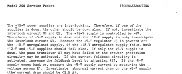
The service manual says the dual 15v power supplies are interlocking so when one goes down the other should as well. If not, one should check U6 and Q5.
This seems to be the case here.
I have no degree in electronics whatsoever but am handy and have a solder station and tester, no oscilloscope.
Can anybody help with what I might do next?
Tthanks in advance
I have isolated the problem to a missing positive rail on the dual+-15v supply. The negative side is fine. All other voltages (5v, 12v...)are also fine.
What I see is U5 has voltaje at the input but nothing at the output.
The service manual says the dual 15v power supplies are interlocking so when one goes down the other should as well. If not, one should check U6 and Q5.
This seems to be the case here.
I have no degree in electronics whatsoever but am handy and have a solder station and tester, no oscilloscope.
Can anybody help with what I might do next?
Tthanks in advance
Attachments
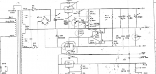
The output of -15 on U2 allows U5 to attain output as the FET Q5 is relaxed.
Input on Q5 and no output ... I would replace Q5 if there is no short circuit across CR23.
Input on Q5 and no output ... I would replace Q5 if there is no short circuit across CR23.
Thank you, Jon. Just to clarify, I saw voltage at the input but not the ouput of the voltage regulator U5. I did not test the Fet Q5, I don´t know if it can be done with a tester.
I checked for continuity across cr23 and there wasn´t any. I don't know if that means a lot.
Should I still replace Q5 before U5?
I checked for continuity across cr23 and there wasn´t any. I don't know if that means a lot.
Should I still replace Q5 before U5?
Last edited:
1) Simply de-solder Q5 and remove it, without replacing it.Should I still replace Q5 before U5?
2) With Q5 removed, if U5 then produces +15V at the output, that means Q5 was defective, and you do need to replace the FET.
3) If U5 still produces no output with Q5 removed, then U5 is faulty, and needs to be replaced. In this case, we don't know (yet) if Q5 was also defective or not; but we are sure U5 is faulty.
4) If you arrived at point (3) and had to replace U5, after replacing U5, you have to decide whether to re-install the same Q5 that you removed, or replace with a new one; until you re-install it, you won't know if it's working properly.
(There are ways to test a JFET with a meter, some resistors, a battery, and a bread-board, but in this case, I think it's simpler and cheaper to just replace Q5.)
-Gnobuddy
Thank you, I removed Q5 and still no output on U5. I have ordered replacements for both but with the current situation, it´s going to be a while until I get them delivered.
Also, the transistor I removed is marked j113 8349 as opposed to the 2n4393 in the schematics. I figure they are equivalents.
Also, the transistor I removed is marked j113 8349 as opposed to the 2n4393 in the schematics. I figure they are equivalents.
Last edited:
JFETs are going slowly extinct, particularly through-hole types. Many older types are no longer available, including most of the types you see in old audio device schematics (MPF102, J201, 2N3819, et cetera.)...J113 8349 as opposed to 2n4393...equivalents.
Fortunately, the last time I checked, the J113 was still in stock at Digikey. (Also its cousins the J111 and J112.)
In this circuit, the JFET is used as a switch, not an amplifier, so the exact type of JFET is not critical. It just needs to turn fully on, or fully off, and just about any JFET will do that.
Is that your cat in your avatar pic? She/he has amazing Siamese blue eyes! 🙂
-Gnobuddy
Code:
Is that your cat in your avatar pic? She/he has amazing Siamese blue eyes!One peculiar thing: The Lexicon has one power supply transformer with two secondaries, one for the dual 15v and another for various smaller voltages. Along with the failure, one of the fuses to the other secondary on the transformer had blown up. I replaced it and, surprisingly, I cannot detect anything wrong there.
Last edited:
I'm sorry - it is hard to lose a pet. My wife and I lost one of our two elderly cats to kidney disease last year. Our second cat (he's the same age) has developed kidney disease this year, so I don't know how much longer we'll have him around. 🙁
Since Lexicon went to the trouble of trying to design a power supply that would only produce +15V if -15V was already present, I have been concerned about ancillary damage that you might find after you fix the problem with the +15V rail. If you're lucky there won't be any. But it is also possible that after the power supply is fixed, you'll find other damage has been caused by the power supply failure itself.
I wonder if the blown fuse on the separate secondary is related to some other failure, triggered by the failed +15V rail.
-Gnobuddy
Sorry for your cat. Hope the other one stays for a long time and that the condition is not too painful.
Here is the schema for the complete power supply. I Will post back when I replace both pieces and, if there's something else wrong, I am sure going to need your help again.
Here is the schema for the complete power supply. I Will post back when I replace both pieces and, if there's something else wrong, I am sure going to need your help again.
Attachments
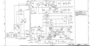
I have replaced U2 and it now reads:
IN: -19 OUT: -1 Adj.: -12.91
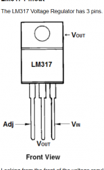
And just found out that U5 is a 7915 and I replaced it with a LM317. I'll remove it, order a 7915 post back when it's replaced.
IN: -19 OUT: -1 Adj.: -12.91
And just found out that U5 is a 7915 and I replaced it with a LM317. I'll remove it, order a 7915 post back when it's replaced.
Last edited:
I was just about to ask if the schematic was correct, as it shows U2 is a 7915.
Hope the new chip solves your problems. Sorry for all your troubles!
-Gnobuddy
Hope the new chip solves your problems. Sorry for all your troubles!
-Gnobuddy
In my incompetence in these matters I had outputs and inputs mixed up all along.
I hope I'll know better next time!
I hope I'll know better next time!
There is always more to learn, and life would be extremely boring if there wasn't!I hope I'll know better next time!
You "gave it a go" as our British friends say, instead of chucking it in the recycling bin, and for that, I applaud you! 🙂
I wonder if there is something wrong with the voltages you report as "1" and "-1". Normally you'll get three or four digit readings from a typical budget-priced digital meter; is the "1" perhaps an error indication of some sort, perhaps that the meter has gone over range and is unable to read the voltage?
-Gnobuddy
Thank you.
I am using the 20v setting pn the meter fpr the readings. I will try a lower setting for that pin later today.
Code:
is the "1" perhaps an error indication of some sort, perhaps that the meter has gone over range and is unable to read the voltage?I put the old U2 back in place. Both outputs give the correct 15v. The 1 reading at the inputs does not change regardless of the meter's voltage setting.
So I have the seemingly correct voltages at the power supply for both analog and digital circuitry yet the unit won't power up.
This vintage Lexicon will light up all LED displays on the faceplate and perform a 12 second test upon rebooting. Now nothing, and no audio coming out at all. Only the fan works.
I've lost hope of fixing it unless someone versed in these units has seen and fixed this problem before.
Attachments
Last edited:
- Home
- Live Sound
- Instruments and Amps
- help with vintage Lexicon power supply