Hey, I recently picked up an ICE Power 100AS2 100W Solid State Power Amplifier Module and I'm trying to build tube preamp for it but having mixed success.
The board itself seems awesome, very strong. Hooked up my signal generator and easily putting out 100W with a 10VAC signal (measured signal to ground).
I built a two stage tube preamp that displays the characteristics I'd like but when I connect the 2 I'm getting significantly lower output power (~40W). Unconnected, the preamp signal can get up to 80VAC (measured signal to ground) but when I attach the tube preamp output to the board's input that signal drops to ~6VAC. I don't have a ton of experience with solid state, but this sounds like an impedance mismatch or something like that?
My 12AX7 has a 100K plate resistor and .022uF coupling capacitor. I've changed the resistor's value (to ground, after coupling cap) from 10K - 1M and nothing really changes. Even removing the resistor didn't do much. Also, I'm taking the output from the preamp at the connection of the coupling capacitor and resistor to ground.
I've done a few calculations and sounds like my output impedance is ~40K...From the ICE's Datasheet, the input impedance is 2.8K, so it sounds like I have greater than the 10x output/input ratio I've seen suggested.
Please let me know if anything I'm doing sounds obviously off. Thanks!
Last edited:
Getting 10v over a 2k8 impedance you need almost 4mA to drive. i would use something like a 6n6p or ecc99 or 6n30p.
Tube preamps will have a difficult time driving 3k with low distortion. The preamp's output impedance should
be under 500R,and also the output capacitor will have to be at least 10uF. You may also need output muting,
to protect the input circuit of the amplifier. Maybe look at some tube headphone amplifier circuits for ideas.
be under 500R,and also the output capacitor will have to be at least 10uF. You may also need output muting,
to protect the input circuit of the amplifier. Maybe look at some tube headphone amplifier circuits for ideas.
Last edited:
You can add a FET input opamp buffer (like TL072, OPA2604) between the tube amp and the ICE Power amp to match the impedance.
You can add a FET input opamp buffer (like TL072, OPA2604) between the tube amp and the ICE Power amp to match the impedance.
So I actually have a few TL072CPs sitting around...given my current tube preamp output impedance and signal amplitude, could you recommend a simple setup for the op-amp? I’ve actually never worked with or designed around them before (typically only tube) so if you could give me the simplest operating setup just to get going I would really appreciate it. Thanks!
That amp is unusual for a SS amp, normally input impedances are expected to be 50k, sometimes lower, down to around 10k.
You need a buffer with a high input impedance, and if the buffer is solid state it needs protection from input over-voltage in your setup.
You need a buffer with a high input impedance, and if the buffer is solid state it needs protection from input over-voltage in your setup.
You can add a FET input opamp buffer (like TL072, OPA2604) between the tube amp and the ICE Power amp to match the impedance.
Or an OPA626... (or AD4627).
So I actually have a few TL072CPs sitting around...
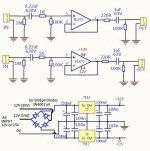
You can try this circuit.
If you sure your tube pre-amp output cap is good enough then you can remove the 0.22uF/630V caps and replace them by 100R resistors.
For the power supply, the circuit runs at low current so that you can use simple zener diodes voltage regulation for the +-12V supply.
Attachments
I don't have my calc handy, but with a 2.8K input R for the amp, a 1uf coupling cap is going to have a cutoff of 1/1ufx2.8K around 350Hz. Probably needs to be closer to 100uF. I'd check if the amp already has a coupling cap and if it does, just remove this one. Also if it really takes 10VAC(rms?) to drive the amp to full power, 12V p/s is not enough (10x1.414). I'd think you'd need to go to 18V if you can, to have 3V of rail to peak output voltage.
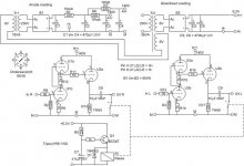
Or use schematic below with 6n6p or ecc99 tube and 200v anode voltage.
I use that with hypex ucd oem modules(imp.1k8). Gain about 11x.
I use that with hypex ucd oem modules(imp.1k8). Gain about 11x.
Attachments
Last edited:
Koifarm is correct. Forgot the 2pi factor in the frequency.I don't have my calc handy, but with a 2.8K input R for the amp, a 1uf coupling cap is going to have a cutoff of 1/1ufx2.8K around 350Hz. Probably needs to be closer to 100uF. I'd check if the amp already has a coupling cap and if it does, just remove this one. Also if it really takes 10VAC(rms?) to drive the amp to full power, 12V p/s is not enough (10x1.414). I'd think you'd need to go to 18V if you can, to have 3V of rail to peak output voltage.

Cutoff with 1uf is 57hz use 4,7 or 10uf
Also if it really takes 10VAC(rms?) to drive the amp to full power, 12V p/s is not enough (10x1.414). I'd think you'd need to go to 18V if you can, to have 3V of rail to peak output voltage.
Yes, they are correct, in order to drive the ICE Power Module, please adjust the output cap and higher power supply voltage.
- Home
- Amplifiers
- Solid State
- Tube Preamp -> Power Amp (Impedance Matching Question)