Please have a look at my description & pics below - any guidance/tips would be great! (this is my second amp, its for a subwoofer)
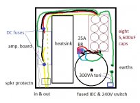
I have settled on this cable routing layout for the parts I am using - it is built on a 300x300mm 3mm aluminium sheet.
the AC starts close (50mm) to the 50-0-50 toroid, then the secondary output gets to the rectifier via about 50mm of wire (twisted), this rectified power goes to the capacitor PCB via about 70mm of twisted wire.
then the power leaves the capacitor bank (which has 100nF capacitor in parallel on both sides) and goes around the top and back down to the amplifier PCB, where there are chassis fuses within 5mm of the PCB power connections.
the 0V of the capacitor PCB goes:
there is a speaker protection circuit right next to the output posts
the input wires will be shielded coax from the back panel that travels about 80mm against the side wall of the chassis.
there is a small 12VDC transformer there for the 80mm TC fan that will sit up at the top in front of the tunnel heat sink - blowing out the rear.
this 12VDC also powers the speaker protection - which will follow the 'up and around' path of the other power wires.
is this wiring plan flawed anywhere or will it be a suitable wiring layout?


I have settled on this cable routing layout for the parts I am using - it is built on a 300x300mm 3mm aluminium sheet.
the AC starts close (50mm) to the 50-0-50 toroid, then the secondary output gets to the rectifier via about 50mm of wire (twisted), this rectified power goes to the capacitor PCB via about 70mm of twisted wire.
then the power leaves the capacitor bank (which has 100nF capacitor in parallel on both sides) and goes around the top and back down to the amplifier PCB, where there are chassis fuses within 5mm of the PCB power connections.
the 0V of the capacitor PCB goes:
- back to the chassis (near but on on the IEC earth bolt)
- to speaker out
- to amplifier 0V
there is a speaker protection circuit right next to the output posts
the input wires will be shielded coax from the back panel that travels about 80mm against the side wall of the chassis.
there is a small 12VDC transformer there for the 80mm TC fan that will sit up at the top in front of the tunnel heat sink - blowing out the rear.
this 12VDC also powers the speaker protection - which will follow the 'up and around' path of the other power wires.
is this wiring plan flawed anywhere or will it be a suitable wiring layout?
Attachments
Looks ok, just keep in mind to separate low current (signal) and high current (speakers, supply) wires to have them connected at one point only. There are good instructions on this platform about this issue.
Looks ok, just keep in mind to separate low current (signal) and high current (speakers, supply) wires to have them connected at one point only. There are good instructions on this platform about this issue.
OK thanks,
yes, read a fair bit on here and elsewhere and looked at many many pictures in build threads...
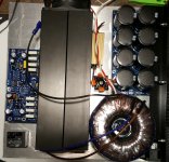
but this layout is fairly unique, don't see many tunnel heat sink setups - so I just arrived at this layout through rearranging everything a few hundred times and thought I'd post it up before drilling into my precious aluminium plate!
Before drilling just make a temp setup with (little) doublesided foam tape to keep the parts in place (connect to chassis where/if possible/needed) and wire it up. A short test tells if it's ok, but you're able to modify from there on.
Nothing glaringly obviously wrong. As MB says, a dry fit test is always a good idea. Masking tape, hot glue are also good for holding pieces in place.
I would consider in-rush protection if using a toroid combined with large capacitance. A soft-start module can be had pretty inexpensively.
I would consider in-rush protection if using a toroid combined with large capacitance. A soft-start module can be had pretty inexpensively.
OK thanks all, the d/s tape idea is good!
I've actually got a ESP p39 soft start from another amplifier that I could use, but was waiting to see how it acted at power on.
I've never had so much capacitors, so I was just waiting to see how it behaves... I might even go to a 500VA toroid eventually, so I guess I should work out the best placement of the p39 now rather than later!
Good one 🙂
Last edited:
- Home
- Design & Build
- Construction Tips
- layout check before I drill & mount parts