Hello,
Recently acquired this gorgeous Threshold SL10 but it sounds flat and clinical in comparison to my Pass korg B1. Like very flat.
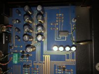
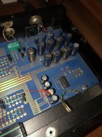
So I had a peak and someone has been here before me. No surprise on an amp this old. Caps need to get replaced so they were. High quality black gate and Panasonic caps used by the looks of it.
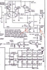
But I noticed one cap in an unusual orientation and performing a simple image comparison shows maybe, just maybe one of these 47uf 50V caps is backwards.
Am I loosing my mind?
Context:
Both are driving Hypex ncore Nc400s with Klipsch Forte 3 at the helm.
Turntable is micro seiki DD40 with nagaoka MP-150.
I really thought the Threshold SL10 was going to hand it to the Pass Korg B1 but maybe I’m just super wrong.
Would love your thoughts.
Thanks and stay safe.
Jules
Recently acquired this gorgeous Threshold SL10 but it sounds flat and clinical in comparison to my Pass korg B1. Like very flat.
So I had a peak and someone has been here before me. No surprise on an amp this old. Caps need to get replaced so they were. High quality black gate and Panasonic caps used by the looks of it.
But I noticed one cap in an unusual orientation and performing a simple image comparison shows maybe, just maybe one of these 47uf 50V caps is backwards.
Am I loosing my mind?
Context:
Both are driving Hypex ncore Nc400s with Klipsch Forte 3 at the helm.
Turntable is micro seiki DD40 with nagaoka MP-150.
I really thought the Threshold SL10 was going to hand it to the Pass Korg B1 but maybe I’m just super wrong.
Would love your thoughts.
Thanks and stay safe.
Jules
Attachments
LOL yeah i get your point "Zen Mod".
I do think that Cap is backwards based on other images online. I will do my due diligence and trace out the PCB with Schematic tonight and post my finding / results.
Thanks a bunch for the replies.
I do think that Cap is backwards based on other images online. I will do my due diligence and trace out the PCB with Schematic tonight and post my finding / results.
Thanks a bunch for the replies.
KB1 is Jessica Rabbit
Funny truth oh yeah B1 Korg sing like Jessica Rabbit

SL10 is Mr. Honesty
Mister Honesty. Who am I?

Hello,
So I went through the schematic and traced out the path on the PCB and yep that capacitor was installed backwards by someone in the past.
I have not changed it out just yet and have a few questions.
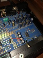
What would this do to the OP amp it was connected to? And further to that what actually is the function of the RC4136N OP amp? I’m just an amateur so sorry for asking silly questions. Is it a feedback loop? How do I measure op and signal to check for any potential problem?
Given the cap was backwards what would the effect on operation be?
To note the caps would have originally been tantalum and have been replaced with the electrolytic caps seen in image.
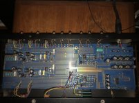
Oh and this PCB outlay and look is just off the charts. Absolutely gorgeous work By Nelson and his team.
Thanks once again for you help and time people.
Stay safe.
Cheers
Jules
So I went through the schematic and traced out the path on the PCB and yep that capacitor was installed backwards by someone in the past.
I have not changed it out just yet and have a few questions.
What would this do to the OP amp it was connected to? And further to that what actually is the function of the RC4136N OP amp? I’m just an amateur so sorry for asking silly questions. Is it a feedback loop? How do I measure op and signal to check for any potential problem?
Given the cap was backwards what would the effect on operation be?
To note the caps would have originally been tantalum and have been replaced with the electrolytic caps seen in image.
Oh and this PCB outlay and look is just off the charts. Absolutely gorgeous work By Nelson and his team.
Thanks once again for you help and time people.
Stay safe.
Cheers
Jules
Attachments
pull it out and align properly
it didn't go Poof!!! only because voltage across it is small - its role is in RC filter of servo circuit, practically enabling servo OP to see just DC of output, filtering out AC
it didn't go Poof!!! only because voltage across it is small - its role is in RC filter of servo circuit, practically enabling servo OP to see just DC of output, filtering out AC
As ZM noted, this appears to be a DC servo. I would probably replace the electrolytic with a tantalum here, as it was originally. Note that tantalums are normally marked with a stripe on the POSITIVE side; possibly why the electrolytic was put in backwards as electrolytics are marked on the negative side.
nope Tantalums
old ones are Popcorns in disguise
new ones (those stacked films etc.) 0 who cares for that when modern electrolytics are better than Tantalums of Yore
old ones are Popcorns in disguise
new ones (those stacked films etc.) 0 who cares for that when modern electrolytics are better than Tantalums of Yore
So I replaced the cap in the correct polarity and put in a new op amp as a precaution.
Sounds the same but glad I did it anyway.
Questions / observations:
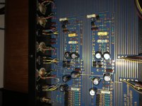
So I have two pre amps. Threshold SL10 and B1 nutube.
Threshold has quoted 20db gain and B1 nutube has 16db gain.
Both driving hypex nc400 mono blocks.
The problem I have is with the B1 I only need to turn the volume up about 1/4 to be really loud. With the SL10 I have to turn it up 3/4 to get anywhere near loud listening levels.
Why is this the case? It seems strange that the SL10 has a much lower output.
Now I haven’t measured anything yet so these are just observations.
Do I have an impedance problem?
Is there some sort of bias setting for the SL10 I need to check?
Is there a service manual or bulletin for the SL10?
Kind of want to dig a little deeper.
Interesting for sure.
Cheers
Sounds the same but glad I did it anyway.
Questions / observations:
So I have two pre amps. Threshold SL10 and B1 nutube.
Threshold has quoted 20db gain and B1 nutube has 16db gain.
Both driving hypex nc400 mono blocks.
The problem I have is with the B1 I only need to turn the volume up about 1/4 to be really loud. With the SL10 I have to turn it up 3/4 to get anywhere near loud listening levels.
Why is this the case? It seems strange that the SL10 has a much lower output.
Now I haven’t measured anything yet so these are just observations.
Do I have an impedance problem?
Is there some sort of bias setting for the SL10 I need to check?
Is there a service manual or bulletin for the SL10?
Kind of want to dig a little deeper.
Interesting for sure.
Cheers
There may be a lot more to it, but could it be the taper on the pots? I have one pre-amp with a pot that has really nice / fine control at lower to mid volumes - but at about 3/4 of a revolution ... it allows things to open up much more rapidly.
You can measure the output of each with a fixed signal and check each at various volume settings including full volume to see.
Glad you've got it going!
You can measure the output of each with a fixed signal and check each at various volume settings including full volume to see.
Glad you've got it going!
rotate pot shaft to approx 50%
measure overall resistance, just to confirm what's written on it, between CW and CCW pins
then measure resistance between mid pin (wiper) and any outer pin
if it's approx 50% ofpot value , you have linear pot , which is completely explaining what you wrote
in any case, write result here.... there is possibly easy solution , if linear pot value is at least 50K
- Home
- Amplifiers
- Pass Labs
- Threshold SL10 is this cap backwards?