on Craigslist for $30. I figured I could use the chassis for a preamp or a chip amp. The amp is an Ultrack KAC1240ME.
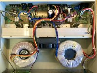
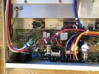
I was a bit surprised to see the two torroidal transformers and the nice heat sink. I have no idea what value the transformers are. Also, they look to be epoxied to the chassis.
What do you think- A home for Bob C’s new chip amps? Maybe a chassis for my Bosoz preamp? Anyone know anything about the trafos?
Attachments
-
 409C4AF2-08C1-464B-82AE-AA730AB78971.jpeg443.2 KB · Views: 409
 -
 FBCBB59D-BC7B-46AA-A71F-3560861E1021.jpeg336 KB · Views: 240
 -
 CCAFC9B0-5621-4AF7-81D1-59C670E3A1C5.jpeg340.1 KB · Views: 234
 -
 B36E6785-7C2A-46FE-AB64-4058ECCC1B4F.jpeg411.8 KB · Views: 370
 -
 804FFD84-76B0-40CA-BF9F-46F564326E88.jpeg385.9 KB · Views: 367
 -
 A3A99335-F170-46BB-8DB1-000A7CCCCFFD.jpeg371.9 KB · Views: 368
 -
 D3D8854E-1FEC-4FB0-86E5-09CD33181AEB.jpeg289.9 KB · Views: 389
One of the transformers is obviously the one that changes the 2.6 ohm output into all the other voltages. The wires go to the terminal strip.
The other produces apparently +-24 dc @ 20A which might be useful for 2.6 ohm speakers but not 8 ohm. Could be regulated to +-15 for op amps but a bit overpowered for a preamp.
Perhaps you can take the bottom off the amp with the transformers glued to it, and replace with sheet metal.
I have a PA amp mixer similar but the direct output is 8 ohm off +-42 rail volts. So it is useful for a single channel 8 ohm organ speaker from organ input with other inputs for radio or CD player.
Last edited:
Thanks, Indianajo.
How can you tell the values for the transformers?
If I was to use one transformer then, I’d want to keep the 24dc @20amps and maybe be able regulate it through the power supply board to a lower voltage to work with a preamp. Is that correct?
I guess with this amp being able to drive a 2 ohm load, it would make a good subwoofer amp as it is. 240watts driving a 2 ohm load.
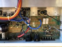
In the top left picture, the transformer on the right has wires going to the IEC socket (120 vac) and the rectifier board on upper right. That makes it the power transformer making the +-20 vdc@20A.
The transformer on the left has red/orange/yellow/brown wires going to the 2.6 ohm 8 ohm 25 v 70 v 100 v terminal strip. It is the impedance matcher probably connected on input to the output transistors.
Yes, if you need a amp for a 2 ohm speaker, this is fine as is. Barring any repair issues. The output transformer may limit performance on high frequencies since these amps are usually used for voice (400-3000 hz) over a building announcement system. But subwoofer service has no high frequencies. The 2.6 ohm output probably comes direct of the output transistors before the transformer.
For converting to a hifi amp, a +-20 vdc supply limits direct connect output to about 10 vac, which is about 8 watts on 8 ohm speaker.
Last edited:
That makes sense, thanks Indianajo. I'm afraid my transformer diagnostic skills don't exist.
I was hoping one of the transformers might be good to salvage for a project. Sounds like the 20VDC/20 A one might be suitable for a lower power project like a preamp. I guess it's worth keeping.
I doubt I'll keep the amps as is. It sounds like they'd only be suitable as a sub amp and I don't have a need.
The good news is that the transformers are epoxy on top, with a bolt and nut attaching them to the base plate. I thought the epoxy might make it hard to remove the bolt and nut, but it turns out if I loosen the nut from the bolt, the transformer pops right off the metal plate.
I think my ideas of using the chassis for a preamp or a chip amp will work pretty well.
> +-24 dc @ 20A which might be useful for 2.6 ohm speakers but not 8 ohm.
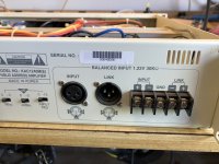
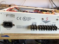
Note the terminals for external 24V DC (single) supply. A truck battery. This amp is sold to squawk even when utility power is down. Emergency alert.
Totem-pole making 240W on 24VDC, 8Vrms, implies 30(!) Amps and 0.266 Ohm load. Possible but not easy.
With a single low-volt supply and a *transformer* (for 25V/70V taps), "obviously" we would use the center-tap power stage today best known from tube amps but entirely practical and once-common in transistors. A (should be) handy reference is GE Transistor Manual from early 1960s. A 12V supply gives 1000mW (1 Watt) at about 230 Ohms end-to-end. 24V same load would give 4W. To get to 240 Watts we must reduce load 60 times, 3.8 Ohms end to end. This is about 1 Ohm and 25 Amps on each side's transistor(s).
Specs are easily found: http://www.ultrakpa.com/pdf/pa/KACseries-20.pdf
I see no reason (if it works) it can't be used as-is, with plain 4 8 and 16 ohm speakers. The low end is claimed as 35Hz--- to give reliable 20Hz response would need BIG iron, and airport/stadium announcement systems don't need that (won't pay that). As I believe a subwoofer should have a high-pass to limit subsonic abuse, and practical home subwoofers do not honestly go below 40Hz, this should be OK. Or full-range, though the technology and market mean it won't be point-oh-oh-oh % THD (<1% @ 1kHz is probably right).
Attachments
Thanks, PRR for the comments and diagram.
I’m learning a lot more about the amp and it’s possibilities. I’ll try it in my system and see how it sounds. Who knows, I might be surprised.
I’m learning a lot more about the amp and it’s possibilities. I’ll try it in my system and see how it sounds. Who knows, I might be surprised.
You can probably get the epoxy to part from the chassis. Try using some cheese wire under the transformer to cut through it
Thanks, jaycee.
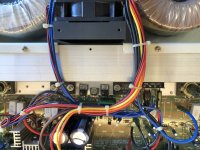
It turns out the epoxy visible on top only sealed the core area. The transformer was not epoxied to the base plate. I was able to loosen the nut on the anchor bolt going through the base plate (not shown in the pics) and the transformer popped right off.
One of the few times where I've feared for the worse and it turned out to be easily solved. Usually, I'm the other way round with my electronics projects.
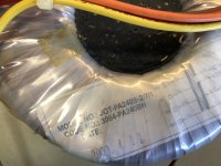
SHOW-THE-TRANSFORMER-LABELS .... IN FULL
So we can see and read the "windings map"
Just the "part number" and at that, from only one of them, is USELESS.
So we can see and read the "windings map"
Just the "part number" and at that, from only one of them, is USELESS.
Thanks, JMF. You are right. I should have posted photos of the windings map and info on the labels.
Here you go-
Transformer 1 is the transformer on right side of the first photo. Notice that someone wrote 2.6 on it in black marker.
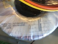
Transformer 2 is the transformer on the left side, with the yellow, orange and red wires.
Here you go-
Transformer 1 is the transformer on right side of the first photo. Notice that someone wrote 2.6 on it in black marker.
Transformer 2 is the transformer on the left side, with the yellow, orange and red wires.
Attachments
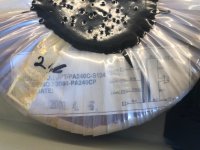
Closer but still unreadable. 😀
Please make little labels , black ink on white paper stating the numbers (say, 240V, 100V, whatever) and put them by the unreadable ones (because of reflections, plastic wrapping, etc.)
From what´s visible, the OT has a centertapped primary, like PRR mentioned, apparently a dedicated NFB winding, and secondariesn of 100V, 70V, 25V and ???????
Power transformer seems to have 2 x 24VAC windings, plus unreadable ones.
Many of these amps, for practical reasons, work with about 36V supplies, and still work fine with 24V (a truck battery or 2 car ones in series) for power OFF emargencies, providing about half rated power which is still ample.
IF the amp works, I´d leave it as-is.
replacing current push pull transformer output amplifier with a regular totem pole output or even a bridged one will mean a gross power loss.
I don't know what you are trying to build. I used a 24v output transformer for this class D amp board:
TPA3251-2CH-140W | 3e Audio. It works great.
Could the 24v power transformer work for that?
TPA3251-2CH-140W | 3e Audio. It works great.
Could the 24v power transformer work for that?
> secondariesn of 100V, 70V, 25V and ???????
Reads fine to me. 100V, 70V, 8 ohms (44V), 25V, and COM.
And why do we care?
Reads fine to me. 100V, 70V, 8 ohms (44V), 25V, and COM.
And why do we care?
Sorry JMF. I thought it would be easier to read, but the light reflection got me.
On the first photo (2.6 written in black marker on the toroid) the missing top line values are- 240VAC, RED, BLUE, 26VAC
For the second photo (yellow, orange and brown wires visible) the missing top line values are- COM, BLACK, BLUE, NF END.
On the first photo (2.6 written in black marker on the toroid) the missing top line values are- 240VAC, RED, BLUE, 26VAC
For the second photo (yellow, orange and brown wires visible) the missing top line values are- COM, BLACK, BLUE, NF END.
- Home
- Amplifiers
- Solid State
- So I bought this old PA amp for the chassis