Obviously being stuck at home gives us all opportunities to get creative so I set out on a journey with some goals:
1. Use up some of my spare parts and tube stash.
2. Create a 5 watt amp, which is all the rage and will also replace my awful solid state shop amp given to me.
3. Utilize this spare Epiphone Century reissue chassis and output tranny.
4. Utilize this mystery smallish power tranny I scored at an estate sale.
5. Create a signal tracer probe to utilize with my new shop amp.
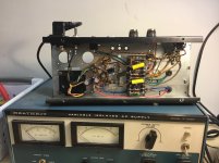
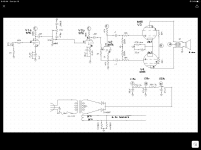
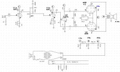
Looking at my tube stash I came across a bunch of 6AS5 pulls. Although the data sheet only gives a Class A example for a car radio, I didn’t see any reason why I couldn’t use these in a push pull setup assuming I can get the screens low enough and the tubes biased correctly. Each tube is around 2.2W, so a PP set of these should yield something close to 5W. Bingo. My power transformer appears to be a 250-0-250 design with only a 6.3v winding. Looks like I will have to go with a solid state rectifier. Here is what I came up with. I realize I am pushing these 6AS5’s beyond their limits but I really like the sound of this amp and will likely leave it unless you all see something egregious. I may add some NFB or may be some tone shaping switches, not sure yet. The screens were the challenge trying to get them down to 110V... I got them close. After about 5 years of repairing gear on the side this is only the second time I have tried to build an amp so be gentle. I really like the way this sounds. Here is the schematic, gut shots and a video of my brother playing it. As a bonus, I noticed these 6AS5’s are on sale for $1.95!
YouTube
1. Use up some of my spare parts and tube stash.
2. Create a 5 watt amp, which is all the rage and will also replace my awful solid state shop amp given to me.
3. Utilize this spare Epiphone Century reissue chassis and output tranny.
4. Utilize this mystery smallish power tranny I scored at an estate sale.
5. Create a signal tracer probe to utilize with my new shop amp.
Looking at my tube stash I came across a bunch of 6AS5 pulls. Although the data sheet only gives a Class A example for a car radio, I didn’t see any reason why I couldn’t use these in a push pull setup assuming I can get the screens low enough and the tubes biased correctly. Each tube is around 2.2W, so a PP set of these should yield something close to 5W. Bingo. My power transformer appears to be a 250-0-250 design with only a 6.3v winding. Looks like I will have to go with a solid state rectifier. Here is what I came up with. I realize I am pushing these 6AS5’s beyond their limits but I really like the sound of this amp and will likely leave it unless you all see something egregious. I may add some NFB or may be some tone shaping switches, not sure yet. The screens were the challenge trying to get them down to 110V... I got them close. After about 5 years of repairing gear on the side this is only the second time I have tried to build an amp so be gentle. I really like the way this sounds. Here is the schematic, gut shots and a video of my brother playing it. As a bonus, I noticed these 6AS5’s are on sale for $1.95!
YouTube
Attachments

Last edited:
Common cathode resistor of output tubes is bad choice. Use separate resistors. It will compensate tube unmatch. Common resistor empasize the possible unmatch.
The OPT is from a PP 6v6 Epiphone Century Anniversary amp that got parted out. The brand is some company in China and there is no data sheet on it. I built this amp awhile ago and it has performed quite well. In fact I have considered building another one with a reverb circuit and placing it in a proper chassis and cab. The concertina appears to work just fine and the shared cathode resistor does as well but I get your concern on using this method with old used tubes.
Doesn't your concertina get in trouble with only 115V supply ?
Mona
Common cathode resistor of output tubes is bad choice. Use separate resistors. It will compensate tube unmatch. Common resistor empasize the possible unmatch.
There are comments about the details, but nobody sees the 233 volts going into tubes rated for 150 volts max?
Hey, it's a guitar amp and it sounds pretty good. If you like it's sound, leave it alone. It's far easier to mess it up than make it "better."
6AS5's can be driven to clipping with maybe 15 volts P-P of drive. In this circuit they will not hard clip, the large screen resistors see to that. They also provide the smooth transition from clean to distortion.
I have made several little guitar amps using old radio tubes. Feeding 233 volts into the plates of 6AS5's will not hurt them as long as you keep the screen grid at or below spec, especially when the amp is driven to clipping.
So far my best efforts with radio tubes is 20 watts from a pair of 50C5's on 340 volts of B+ and 30 watts from a pair of 50L6's, also on 340 volts. In both cases the screen grid is running 120 volts or less.
For those that like to play with these tubes, the 50L6, 12L6, and 25L6 are 6W6GT's with a different heater. The 35L6 is not the same tube and it doesn't like being abused in this manner.
the 50C5, 25C5, 17C5, 12C5 and 6CU5 are all similar tubes with a smaller plate to fit in a 7 pin bottle. Again, the 35C5 is not the same.
All of these tubes have a 7.5 watt heater. This makes for serious cathode emission and therefore a low saturation voltage. These characteristics are the key to the big power output, behaving much like a TV sweep tube, which the 6W6GT is. Keep the plate dissipation below 10 (continuous) to 12 (on brief peaks) watts on the 7 pin tubes, and 12 to 14 watts on the octals. Keep the screen grid at or below rated dissipation at all times.
With 7.5 watts in the heater and 10+ watts burned in the plates, these tubes, especially the 7 pin versions will get HOT! That's normal. The "typical operation" values given in the data sheet have it operating in class A at 110 volts and 50 mA for 5.5 watts of plate dissipation. That's 100% of it's max spec, and these little tubes lived in radios that saw many hours of continuous play a day, for years! When the little radio died due to a weak tube, it was almost always the 35W4 rectifier tube, not the output tube.
The 6AS5 has a lower powered heater, and therefore lower maximum output power.
Thanks for such a detailed reply. I fully understand that I'm pushing these tubes to the limit in a couple of ways but such is the case with many guitar amps. I have a ton of these tubes which affords me some leeway to experiment. I'm still unsure on the power transformer. This thing is small (physically smaller than my OPT) and the markings don't equate to any EIA code that I can tell. That being said, it doesn't get hot which gives me some assurance it's not being overloaded.
- Home
- Amplifiers
- Tubes / Valves
- Push Pull 6AS5 Build