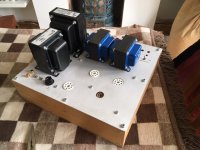
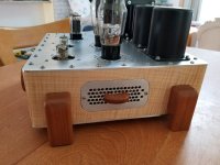
True, she's not much to look at. It was my first project and I was expecting it to blow up when I switched it on for the first time so I didn't put too much thought into the cabinet, or anything much really, as you can see. But it worked a treat from the get go and I loved the sound so much, and was lazy, so there it stayed for nearly ten years.
Now it's dead.
First the right channel would drop out sometimes, then reappear. Eventually it stopped working altogether. I put it down to ten year old tubes so I replaced the lot. No change, still just the left channel. Then that promptly died too, and the fuse blew.
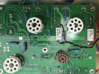
I've turned it upside down and got the toolbox out, but it was a long time ago and I don't know what I'm looking at any more. I've checked obvious things like physical connections and they're fine, or at least look it. Nothing obviously cooked that I can see. I'm just about to remove the board and have a look at the other side.

Now it's dead.
First the right channel would drop out sometimes, then reappear. Eventually it stopped working altogether. I put it down to ten year old tubes so I replaced the lot. No change, still just the left channel. Then that promptly died too, and the fuse blew.
I've turned it upside down and got the toolbox out, but it was a long time ago and I don't know what I'm looking at any more. I've checked obvious things like physical connections and they're fine, or at least look it. Nothing obviously cooked that I can see. I'm just about to remove the board and have a look at the other side.
Attachments
Do you access to an oscilloscope ?
It would be useful to know which stage has failed.
Even checking the voltages around each tube may tell a story.
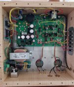
There is a fair bit of flux around your work, it might be useful just to clean that off with some IPA. (Not the beer variety)
Those caps look modern, I think it would be unlikely for one to have failed. The same with the resistors.
It would be useful to know which stage has failed.
Even checking the voltages around each tube may tell a story.
There is a fair bit of flux around your work, it might be useful just to clean that off with some IPA. (Not the beer variety)
Those caps look modern, I think it would be unlikely for one to have failed. The same with the resistors.
Last edited:
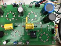
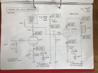
Both channels died? Sound like its power supply related to me. Did you check the transformer secondary voltage along with the rectified ? Schematic? I think a simple VOM would diagnose the problem. The flux on the board bothers me along with the nuts for standoffs. I would look for some plastic to replace the nut that comes in contact with the board.
It seems odd that one channel would drop out and now both have failed.
Check the voltages around the valves.
Check the voltages around the valves.
Last edited:
...consider re-flowing all of the solder joints on the board....won't take that long...just touch each one with the hot iron....
You likely have other issues but this sometimes can make channels drop out when everything heats up/expands.
You likely have other issues but this sometimes can make channels drop out when everything heats up/expands.
You used a Supertex part instead of the specified Ixys10M45S?
Might check those to see if they have failed.
Might check those to see if they have failed.
Thanks for the helpful replies!
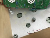
I know it’s not pretty - I had forgotten quite how rough my work was. Made me a bit embarrassed to share the photos but we all start somewhere I guess. Yes, particularly using the bolts as spacers was not my finest hour. When I built it I was living in crappy apartment in south London and it was the best I could do. Or perhaps that’s a lame excuse and I just got impatient...
Anyway, I measured all the voltages in the same way I did a few posts earlier, and they were virtually identical...so the amp is performing just as well.
SOLVED! 🙂
The culprit was one of the input jacks making a dodgy connection. Temporary fix in place whilst I listen to it for the first time in months, possibly with a contented smile on my face and beer in hand!
This is a great project for any novice (me included). I found it quite a steep learning curve but hugely rewarding. But it would never have happened without the support of this community.
Now time, and plenty of it, to give the chassis the respect it deserves.
Thanks everyone,
Mark
Hey Mark, glad you got it sorted out and that it wasn't something more serious. You've nothing to apologize for on the subject of building; you did a good job overall and obviously learned a lot in the process. Heck, the fact you've been using it for the past nine years speaks volumes, because most people never even get past the dreaming stage. 🙂
I'll let you in on a little secret: pictured below is the top and underside of a Tubelab SE-II I built last year. To promote convective cooling I mounted the main PC board to a sub-plate, then attached both of those to the underside of the main (or "top") chassis plate, for three layers in all. And separating them all are... nuts. The only thing I did differently was to drill out the threads of the ones I was using for spacers. Great minds think alike!
I even had a similar occurrence with one of my input jacks, which developed a dodgy, intermittent connection at an inopportune moment (a public display). But... that's a story for another time.
I'll bet that beer never tasted so good! 😀
Attachments
Thanks Win. It's actually waxed thread for use in a Speedy Stitcher awl. You can order it online, but I got mine at REI.
- Home
- More Vendors...
- Tubelab
- After nine faithful years my beautiful sounding SSE DIED last night. Please help!