Anyone have any experience with this amp oscillating? I can see it at the input and output. A 10K load and oscillation returns.
I short the input and oscillation goes away. Hard to tell since it could be coming from feedback loop via the output. I think Q1/Q2 FET is bad since it appears these have been replaced with a single package unit and the short to ground at input makes the oscillation null at output.
Some diodes were removed as a mod(Roy Esposito's mods), not sure if these mitigate oscillation or not. Also, C6,C7 look like different parts compared to left channel but are .1uf parts, these tie mosfet drain to gnd at output.
Link to Schematic

The biasing scheme for VAS/drivers Q3/Q4 is rather odd(*) - any change in the supply voltage will strongly affect the biasing here - under-biasing here might cause oscillation.
(*) I could use strongly language here!
(*) I could use strongly language here!
The biasing scheme for VAS/drivers Q3/Q4 is rather odd(*) - any change in the supply voltage will strongly affect the biasing here - under-biasing here might cause oscillation.
(*) I could use strongly language here!
Hmm, i wonder if the bias pot is causing the issue?
Oscillation is around 50khz.. Both channels seem to be slightly biased into Class A since heat sinks get pretty warm. But the bad channel may be getting that warm due to the oscillation and might be under biased like you said.
The zener in series with Q4 seems odd, i dont recal ever seeing this in another amp.
Last edited:
Well, its not the bias, i played around with bias and no change
When i connect a 47k dummy load to input, the oscillation drops to 2khz.
I really think the Q1/Q2 FET is damaged. Its difficult to disconnect feedback to check if the outputs are causing the issue
When i connect a 47k dummy load to input, the oscillation drops to 2khz.
I really think the Q1/Q2 FET is damaged. Its difficult to disconnect feedback to check if the outputs are causing the issue
I don't mean the output stage bias, I mean the drivers/VAS bias. Check the voltage across R12 or R15 to see what the bias is for that stage. It is very sensitive to D5 and the supply voltages from the circuit topology - if the voltage rails have issues this bias may be way out.
4.5v across both R12 and R15
D5 reads 30v
Good channel has 5.9v across R12,15
Bad channel pulling more current but i suspect its the oscillation
There is a 1v difference between pos and neg supply
Neg supply -23v vs 24v on pos side
D16 is a Off slightly
D5 reads 30v
Good channel has 5.9v across R12,15
Bad channel pulling more current but i suspect its the oscillation
There is a 1v difference between pos and neg supply
Neg supply -23v vs 24v on pos side
D16 is a Off slightly
Last edited:
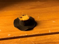
Resolved!!
Just found the problem, driver FET was loose and has excess glue on pin
I was able to wiggle it and oscillation was reduced(it also got worse and bias went up enough to blow fuse), still has a bit of a connection issue. I thought those were transistor spacers on the board, not transistor sockets!!
Have never seen those before now.
Attachments
deafbykhorns,
Would you happen to have any good pictures of the amplifier PCBs of this amp and measurements of voltages across R5, R8 and R13?
Thanks either way!
mlloyd1
Would you happen to have any good pictures of the amplifier PCBs of this amp and measurements of voltages across R5, R8 and R13?
Thanks either way!
mlloyd1
Thanks. I wasn't looking to do a repair; I am toying with building a clone of an Acoustat TNT200/120 or Hafler 9500/9300 and wanted to verify my estimates of the voltages and currents in the driver stage. I know in the earlier Transnova design notes that Jim Strickland released, he mentioned that the transistors driving the MOSFETs were set to run much higher currents than usual. I guess that's partly because the output stage MOSFETs have voltage gain now (i.e. not simply source followers anymore), so you lose the benefit of bootstrapping of the input capacitance and need to compensate for that ....
- Home
- Amplifiers
- Solid State
- Acoustat TNT 200 amp oscillating