Hi,
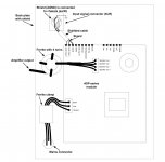
Assembling my 500ASP amp, I am a little confused on where and how wire the ground/earth. According to the amp's manual, the 3 pin input connector on the amp (earth, line and neutral) goes to the mains IEC connector.
But, what about the earth pin in the IEC connector? It goes to the chassis (unpainted part) and also to the amp's earth connector?
Also, I am using balanced input... and according to the manual the pin 1 of the XLR input connector is also connected to the chassis. Is this correct? Or I can omit the use of the "fourth" pin on the XLR input.
Any help would be greatly appreciated.
Attachments
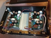
UPDATE:
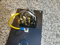
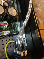
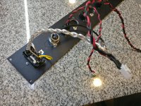
I build it with the amp's earth connector to the IEC and the IEC to the chassis.
The mains are twisted with the ground.
Input XLR connector's pin 1 are connected to the chassis.
I build it with the amp's earth connector to the IEC and the IEC to the chassis.
The mains are twisted with the ground.
Input XLR connector's pin 1 are connected to the chassis.
Attachments
Grounding has some solid rules and some that are "floating".
So, if you have a metal chassis and a mains connection with safety earth, these have to be connected. That is solid.
Now comes the tricky part, the audio ground.
Your XLR connectors body has contact to the chassis. Hot and cold (the signal wires) go to the amp. The XLR ground can be connected or left open. This depends on the whole construction. First you should connect it to audio ground of the amp (which is usually not IEC ground, even if it measures as solid connection!).
Now try your amp, if it is silent, fine. If not, try to open up the XLR ground. Sometimes you even find a switch at the back of an amp, as one pre amp may need a different scheme than another.
There is usually some version that works best. It depends...
Sometimes for example, signal ground to chassis ground over a (maybe 10-100 Ohm) resistor, in parallel with a capacitor gets you noise free.
This is no solid ground you stand on, if you build "your" amp. Nice when the designer gives you clear advice how it should work best. ICE does.
So try to do it as you wrote, AGND to XLR to chassis. Sometimes the IEC ground to chassis is made by the fixing holes with a metal distance keeper. Then you should not ground the IEC connector, but the fixing bolts for earth.
The picture does not clearly state how it is done, so your confusion is understandable. Use a Ohm meter to check it out.
If using the signal ground as chassis IEC ground works without hum, do as they pictured. If the amp is silent and safe, fine. If not, try alternatives.
Good luck!
Last edited:
xlr pin1 is solely a cable shield an should not be connected to audio ground since there is only error current there. Pin1 can be left open, or connect directly to chassis close or at the xlr connector to provide low impedance for these error currents to exit (mains safety ground) and not to enter audio circuitry. Cable shield is basically extension to the device chassis. If both devices at each end have pin1 connected, there is a ground loop through IEC safetygrounds and the connecting pin1 between the devices. One can then detach the pin1 from either end to break this ground loop. I think in studio environment, the outputs of devices are normally left pin1 open, and the inputs have pin1 connected.
Last edited: