Having some trouble with this amp, when I give it +12 on the remote the amp tries to pull what I assume is excessive current. (I have my bench top power supply set to 3 amps.) The power supply will pulse on and off trying to build rail voltage but not achieving it. I never get a square drive wave on the gates.
I removed the rectifiers, the power supply no longer pulses and the amp only draws a little bit of current on start-up. There's a good drive wave on the PS gates at start up but it disappears very quickly and the current draw falls back to near zero.
The rectifiers tested OK; no shorts, not open, passing current in the correct direction.
One of the output FETs is no good, the other 3 check out OK on my multimeter. With the outputs pulled from the board and the rectifiers back in the amp returns to a state of pulsing, failing to build rail voltage.
The only components generating heat are the PS FETs which get warm but I also have not left it running for more than a minute.
Does anyone have a suggestion of where to look next? I was not prepared to find a TDA7570 driving the outputs.
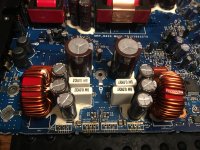
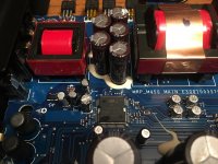
Attachments

Compare the resistance readings between the legs of the output transistors. Check all combinations.
Do the readings from the two N-channel FETs match?
P-channels?
Do the readings from the two N-channel FETs match?
P-channels?
Perry, do you sleep? Seems like you're answering questions on here around the clock. (no I am absolutely not complaining)
IRF5305 P Channel:
Both:
9.9 Meg ohm and 9.7 Meg ohm between legs 2 and 3, red on 2 & black on 3.
All else reads open.
IRFZ44N N Channel:
First:
9.85 Meg ohm between legs 2 and 3, black on 2 & red on 3
All else reads open.
Second:
50 ohm, black on 1 & red on 2
6 ohm, black on 1 & red on 3
47 ohm, black on 2 & red on 3
53 ohm, red on 1 & black on 2
6 ohm, red on 1 & black on 3
45 ohm, red on 2 & black on 3
Sleep disorder. I sleep a bit here and there.
Was the 'second' the channel with the failed FET?
The low readings would seem to indicate that the driver IC is defective. See if anything else could be causing the low readings.
Was the 'second' the channel with the failed FET?
The low readings would seem to indicate that the driver IC is defective. See if anything else could be causing the low readings.
I misunderstood your instructors, those are the measurements of the FETs out of the board. I will update with the correct information later today.
Would you like the FETs reinstalled when I measure the board?
Would you like the FETs reinstalled when I measure the board?
PSU limited to 3A ? I think that might be your problem. The amplifier might need more than that during initial power up.
Last edited:
No. I'm trying to see if the FET damaged the driver. If both channels read the same, it may have survived. If not, and there are no defective components between the FET pads and the IC, it may have failed.
I considered this so I compared the behavior to other similar Alpine amps I have on hand. The other amps bounce off the current limit once while charging the rail caps then sip current. The one I'm working on slams against the limit continuously and doesn't build rail voltage.PSU limited to 3A ? I think that might be your problem. The amplifier might need more than that during initial power up.
No. I'm trying to see if the FET damaged the driver. If both channels read the same, it may have survived. If not, and there are no defective components between the FET pads and the IC, it may have failed.
Here are the measurements you requested:
Positive speaker terminal pair:
IRFZ44N (N channel FET)
black on 1 & red on 2: 103k
black on 1 & red on 3: 98.7k
black on 2 & red on 3: 5.29k
red on 1 & black on 2: 104.8k
red on 1 & black on 3: 99.5k
red on 2 & black on 3: 5.29k
IRF5305 (P channel FET)
black on 1 & red on 2: 5.35k
black on 1 & red on 3: 54.3
black on 2 & red on 3: 5.29k
red on 1 & black on 2: 5.35k
red on 1 & black on 3: 54.2
red on 2 & black on 3: 5.29k
Negative speaker terminal pair:
IRFZ44N (N channel FET) <----- This was the location of the bad FET
black on 1 & red on 2: 5.31k
black on 1 & red on 3: 31.4
black on 2 & red on 3: 5.28k
red on 1 & black on 2: 5.31k
red on 1 & black on 3: 31.3
red on 2 & black on 3: 5.28k
IRF5305 (P channel FET)
black on 1 & red on 2: 5.28k
black on 1 & red on 3: 13.5
black on 2 & red on 3: 5.29k
red on 1 & black on 2: 5.28k
red on 1 & black on 3: 13.3
red on 2 & black on 3: 5.29k
Considering how different my measurements are for the N channel FETs I'm guessing the TDA7570 is smoked which is a shame. Those chips are impossible to find from a reputable vendor.
When I have more time I'll check all the passives between the 7570 and the outputs to see if one of them is out of spec.
Possibly a dumb question, is it safe to power the amp with the TDA7570 removed? My thought is that if the excessive current draw goes away with it pulled then it's almost certainly the culprit. (Provided all the passives check out.) The giant solder pad on the bottom could be why it isn't getting hot during my limited run time.
Thanks for being so thorough.
I'd expect the outputs to be like the top z44. The 54 ohm readings on the top P-channel are odd... maybe not for this IC.
The low readings on the lower FETs are not much different than the gate resistors so the IC could well be shorted.
I'd expect the outputs to be like the top z44. The 54 ohm readings on the top P-channel are odd... maybe not for this IC.
The low readings on the lower FETs are not much different than the gate resistors so the IC could well be shorted.
Thank you. I appreciate your input, Perry.
Guess I'll be putting this one aside for now. I have another TDA7570 driven amp to go through that I can compare those measurements with. Might end up taking a shot at a replacement IC from one of the Chinese vendors. If I ever get this one sorted out I'll come back to update the thread. In the meantime I have a few more amps to go through so stay tuned for more threads full of fng questions.
Guess I'll be putting this one aside for now. I have another TDA7570 driven amp to go through that I can compare those measurements with. Might end up taking a shot at a replacement IC from one of the Chinese vendors. If I ever get this one sorted out I'll come back to update the thread. In the meantime I have a few more amps to go through so stay tuned for more threads full of fng questions.
Last edited:
- Home
- General Interest
- Car Audio
- Alpine MRP-M450 repair help