I have a "new to me" C375BEE.
At low to mid volumes, it works perfectly.
At elevated volume levels (I'd estimate in the area of 10W and higher), the right channel becomes distorted (the distortion increases with volume level, and is most noticeable at lower frequencies) and (if pushed a bit further into the audible distortion) will trip the amp's protection circuitry, requiring a full power cycle. I don't think it's an over-temp situation (the amp really isn't getting that warm) so I am guessing there is some detection for DC / clipping / heavy distortion on the outputs and that's what is triggering the protection circuitry.
So far I've eyeballed it, and found no obviously failing caps, although most of the cap brands are straight from the junk list (Lelon, Jianghai, ...) which is a real shame for an amp that retailed for four figures.
I'm wondering what ya'll think. Should I just go through and recap this thing and odds are the problem will be fixed, or does this sound like a failure that I need to diagnose? Any recommendations?
Last edited:
Initial observations in idle conditions, inputs shorted, outputs disconnected:
the left channel (the one that sounds fine) has 0.00V on the outputs. The idling current (as checked by measuring a voltage between the indicated test points) is within spec (6.5mV +/- 1.1mV). The ISC Sensitivity (I don't know what this is) is ever so slightly out of spec (measures 60mV, spec is 0mV +/- 50mV).
The right channel has 0.41V on the outputs. The idling current appears to be 0 (0.00V measured between the designated pins). The ISC sensitivity is "dead on", also measuring 0.00V.
I added a 6 ohm resistive load to the right channel output, and the output voltage remained.
Last edited:
0.4V is too high an offset, there's something up with the right channel, presumably causing it to clip. Check its getting all its power rails at the same voltage as the left amp is.
I'd recommend disconnecting the speakers - even though the protection seems to be working,
better safe than sorry.
I'd recommend disconnecting the speakers - even though the protection seems to be working,
better safe than sorry.
I checked the power rails going into each of the two amp boards, and the rail voltages were identical to both.
rail measurement
VCC +72.2
VSS -72.2
+80V +90.1
-80V -91.0
+15V +15.5
-15V -15.4
rail measurement
VCC +72.2
VSS -72.2
+80V +90.1
-80V -91.0
+15V +15.5
-15V -15.4
Looks like I have my first task: repair the right channel bias circuit. The pot doesn't do anything (can't get a reading between the test points no matter the setting). Left channel responds as normal to the bias pot.
I just remembered that the 375BEE and 275BEE share the same amp boards, and I found some info online (googled "NAD C 275BEE Idle Current Adjustment") for a 275BEE that had the same problem. Apparently heat kills some of the resistors in the bias circuit. I will check/replace those and go from there and post back...
I just remembered that the 375BEE and 275BEE share the same amp boards, and I found some info online (googled "NAD C 275BEE Idle Current Adjustment") for a 275BEE that had the same problem. Apparently heat kills some of the resistors in the bias circuit. I will check/replace those and go from there and post back...
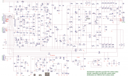
Measure right channel Q133 transistor C-E voltage and compare with left channel, check the BIAS circuit Q152 and Q133 and components around.
- Home
- Amplifiers
- Solid State
- NAD C375BEE repair help